DEFOGGERS
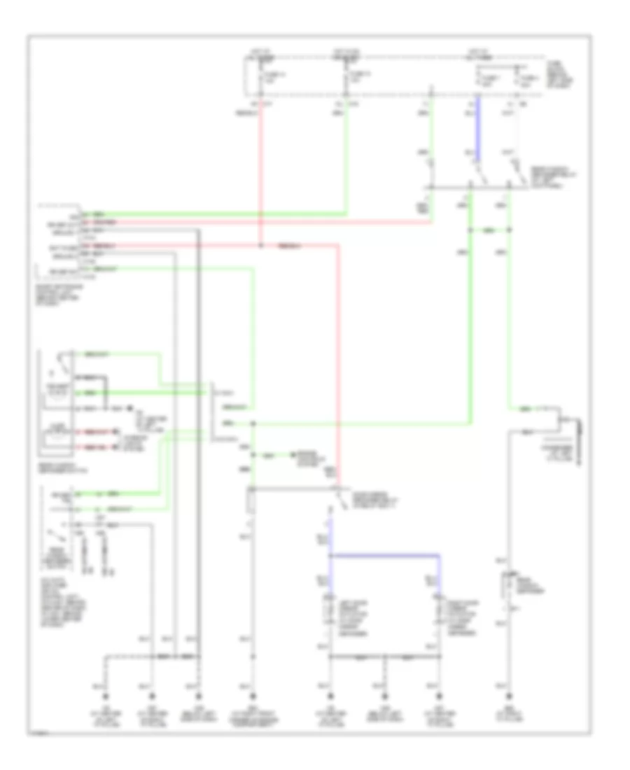
Defoggers Wiring Diagram for Nissan Maxima SE 2003
List of elements for Defoggers Wiring Diagram for Nissan Maxima SE 2003:
- (w/ door
- 10a
- 12l m19
- 20a
- 20a
- 8k m17
- A/c
- A/c auto amplifier (or a/c control unit) (w/o nav: behind center of dash) (w/ nav: behind lower center of dash)
- B11
- B62 (at right ``c" pillar)
- B81
- Bat (fuse)
- Condenser (at left ``c" pillar)
- Defogger)
- Door mirror defogger relay (in relay box 1)
- E53 (at right front corner of engine compartment)
- Engine controls system
- Fuse 10
- Fuse 13
- Fuse 4
- Fuse 7
- Fuse block (behind left side of dash)
- Ground 1
- Ground 2
- Hot at all times
- Hot in on or start
- Ign
- Illum
- Ind lamp
- Interior lights system
- Left door mirror actuator
- M143
- M144
- M145
- M25 (below left side of dash)
- M56
- M57
- M60
- M87 (at center of right ``a" pillar)
- M9 (at center of left ``a" pillar)
- M9 (at center of left ``a" pillar)
- Mirror
- Nca
- Rear window defogger
- Rear window defogger relay (at left kick panel)
- Rear window defogger switch
- Right door mirror actuator (w/ door
- Rr def f/b
- Rr def out
- Rr def sw
- Smart entrance control unit (behind center of dash)
- W/ automatic
- W/ navi
- W/o automatic
- W/o navi
 English