ELECTRONIC POWER STEERING
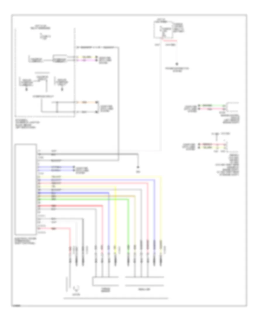
Electronic Power Steering Wiring Diagram for Mitsubishi Lancer Ralliart 2011
List of elements for Electronic Power Steering Wiring Diagram for Mitsubishi Lancer Ralliart 2011:
 English
Electronic Power Steering Wiring Diagram for Mitsubishi Lancer Ralliart 2011
List of elements for Electronic Power Steering Wiring Diagram for Mitsubishi Lancer Ralliart 2011: