ENGINE PERFORMANCE
2.5L
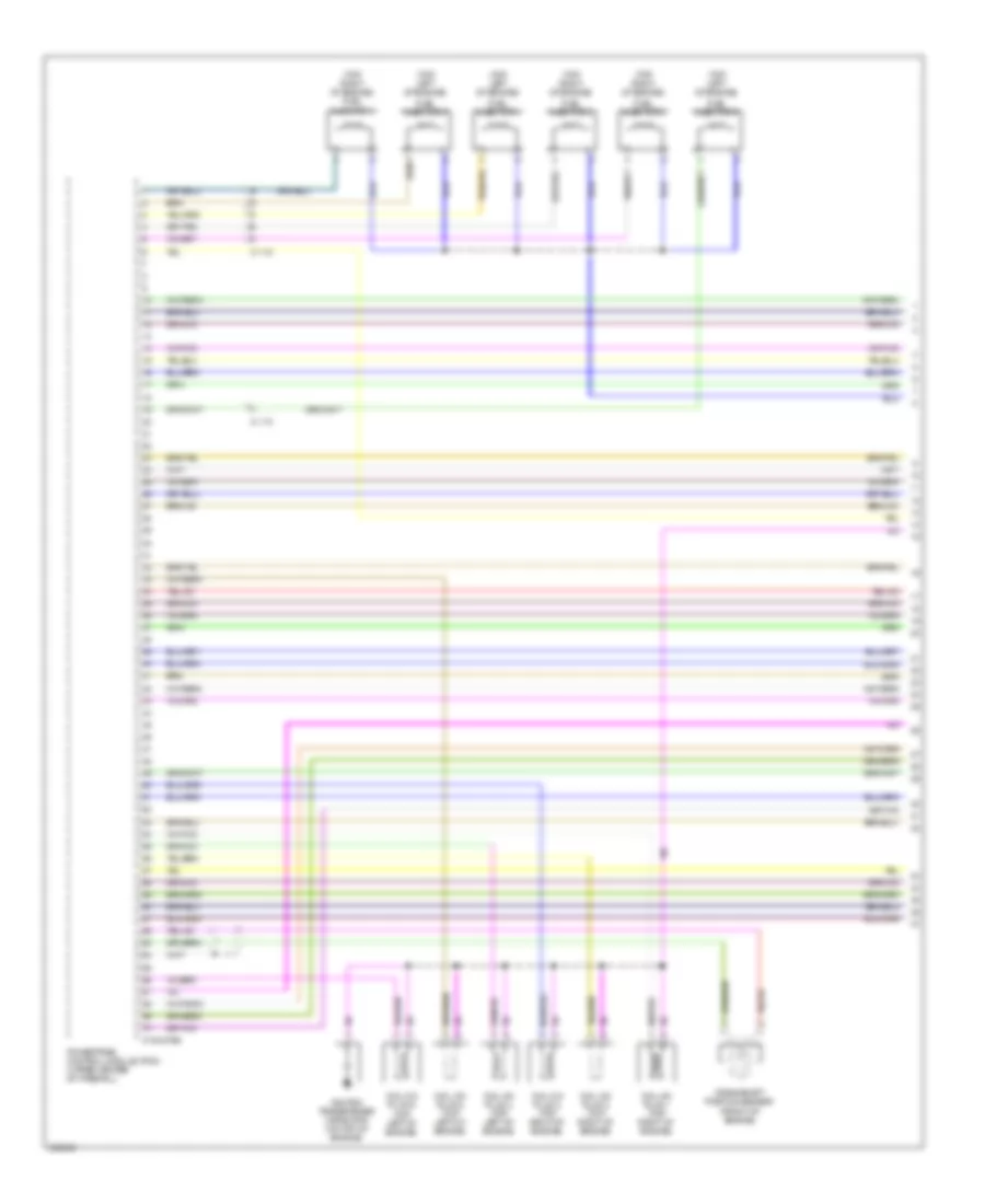
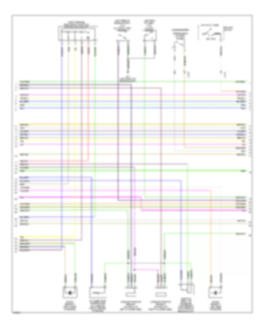
2.5L, Engine Performance Wiring Diagram (1 of 4) for Mazda Tribute i Grand Touring 2011

List of elements for 2.5L, Engine Performance Wiring Diagram (1 of 4) for Mazda Tribute i Grand Touring 2011:
- (top of engine)
- (top of engine) electronic throttle control motor
- 0140-175e
- Acc
- C-211
- Camshaft position sensor (on left rear of cylinder head)
- Coil on plug 1 (top right of engine)
- Coil on plug 2 (top right of engine)
- Coil on plug 3 (top right of engine)
- Coil on plug 4 (top left of engine)
- Crankshaft position sensor (front of engine block)
- Cylinder head temperature (cht) sensor (on right front of cylinder head)
- Fuel injector 1
- Fuel injector 2
- Fuel injector 3
- Fuel injector 4
- Hot at all times
- Ignition switch
- Ignition transformer capacitor (on top of engine)
- Knock sensor
- Manifold absolute pressure (map) sensor (front of engine compt)
- Off
- Powertrain control module (pcm) (upper center of firewall)
- Run
- Start
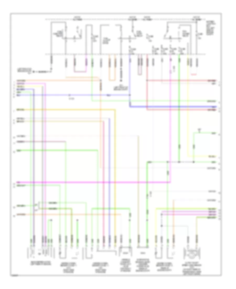
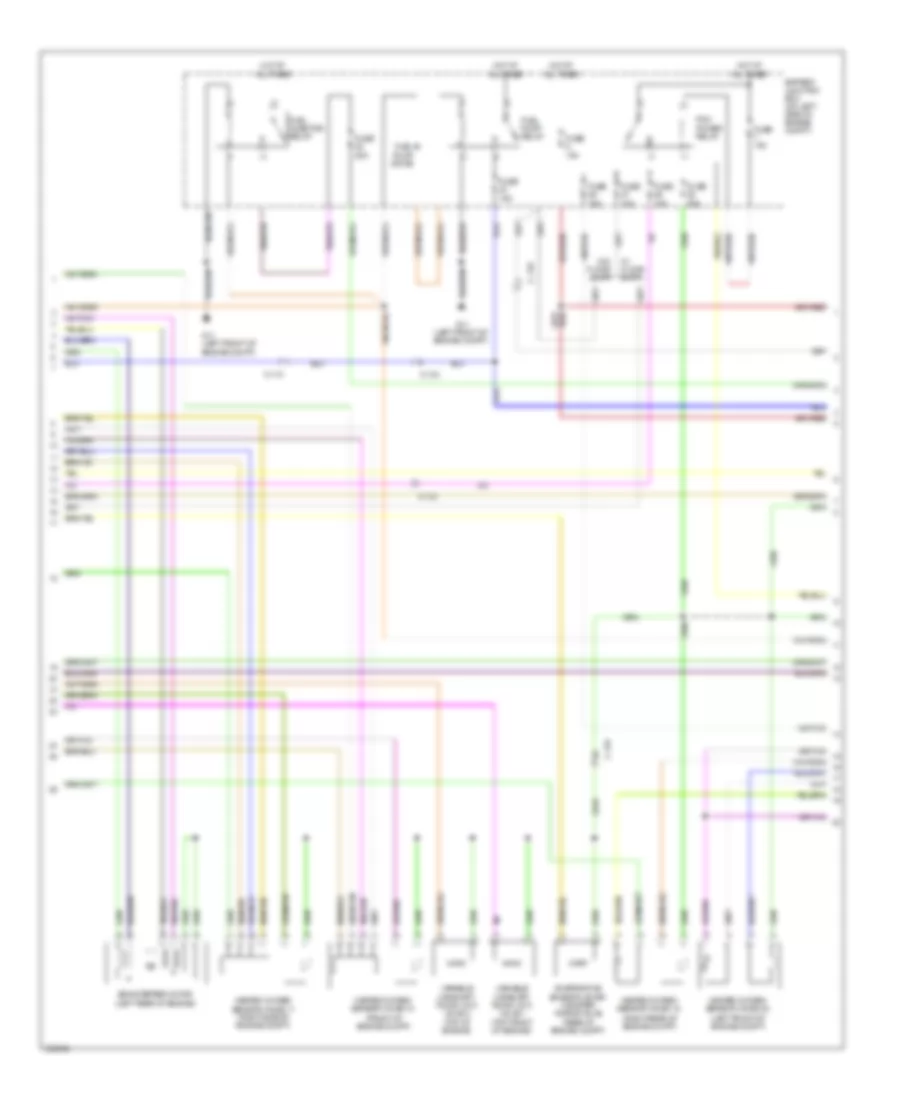
2.5L, Engine Performance Wiring Diagram (2 of 4) for Mazda Tribute i Grand Touring 2011
List of elements for 2.5L, Engine Performance Wiring Diagram (2 of 4) for Mazda Tribute i Grand Touring 2011:
- (left front of engine compt) g11
- (rear of engine compt)
- A/t
- Battery junction box (on left side of engine compt)
- C-133
- Egr stepper motor (left rear of engine)
- Evaporative emission (evap) canister purge valve (rear of engine compt)
- Fuel injector relay
- Fuel pump diode
- Fuel pump relay
- Fuse 10a
- Fuse 15a
- Fuse 20a
- G11 (left front of engine compt)
- Heated oxygen sensor (ho2s) 11 (a/t) (right side of engine)
- Heated oxygen sensor (ho2s) 11 (m/t) (right side of engine)
- Heated oxygen sensor (ho2s) 12
- Hot at all times
- M/t
- Output shaft speed (oss) sensor (m/t) (on right rear of transmission, near left axle flange)
- Pcm power relay
- Variable camshaft timing (vct) valve (top front of engine)
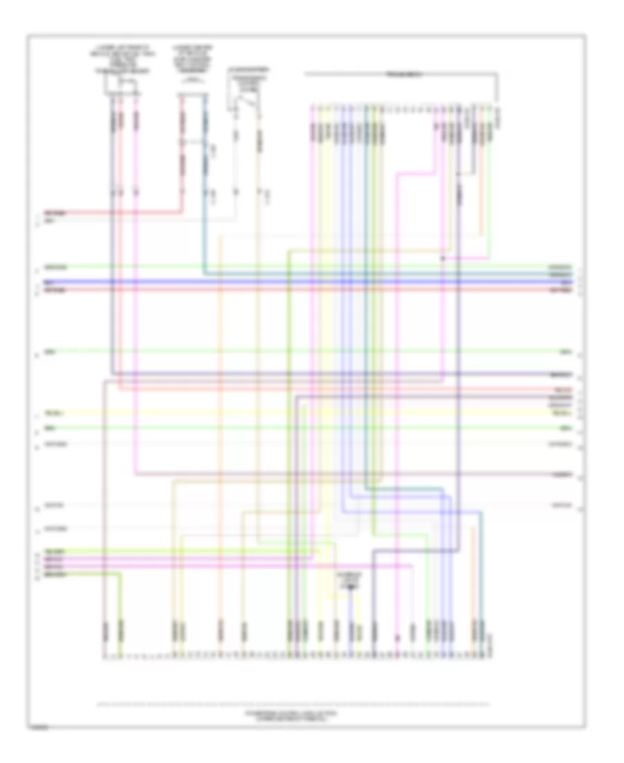
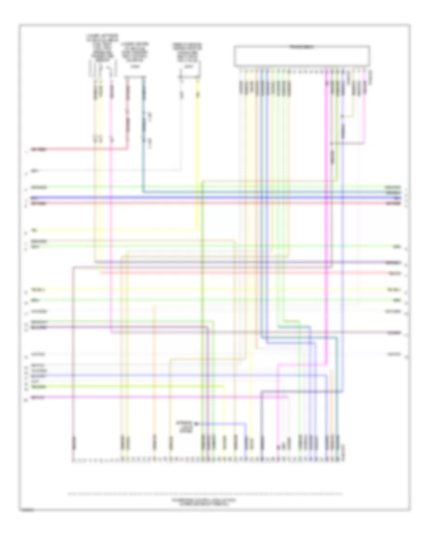
2.5L, Engine Performance Wiring Diagram (3 of 4) for Mazda Tribute i Grand Touring 2011
List of elements for 2.5L, Engine Performance Wiring Diagram (3 of 4) for Mazda Tribute i Grand Touring 2011:
- (under center of vehicle) evap canister vent control solenoid
- (under left rear of vehicle, above fuel tank) fuel tank pressure transducer sensor
- 0140-131
- 0140-132
- 0140-175t
- C-210
- C-212
- C-327
- Exterior lights system
- Floor shifter
- Powertrain control module (pcm) (upper center of firewall)
- Transmission
- Transmission control switch
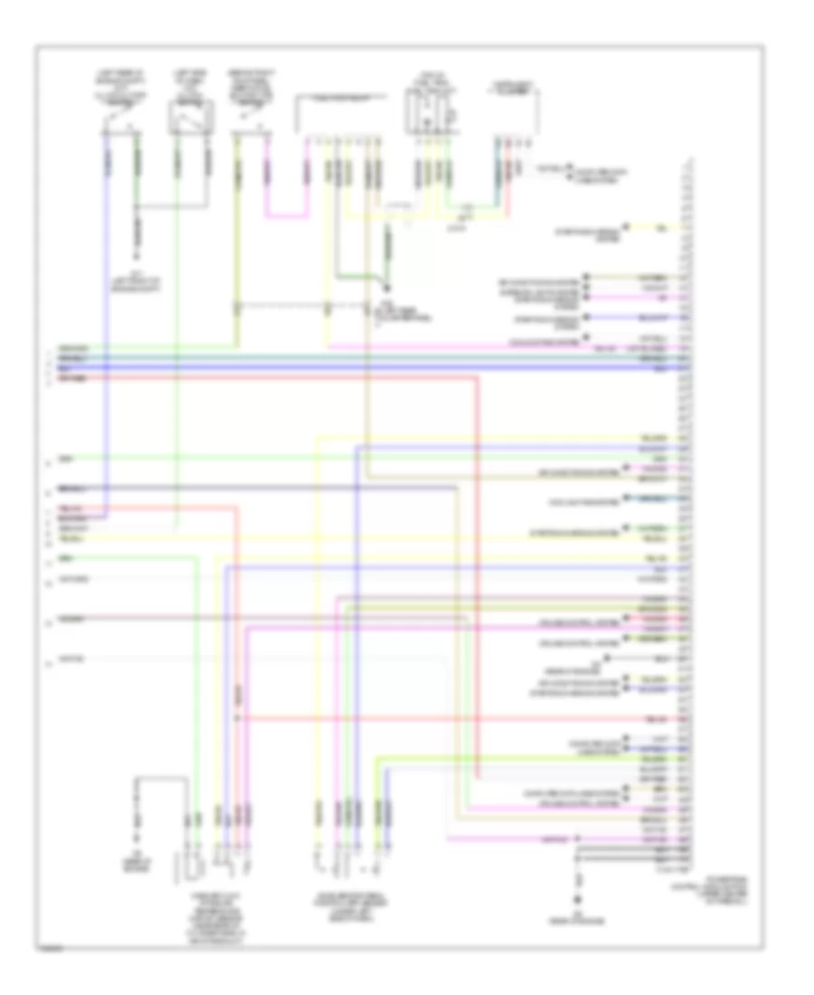
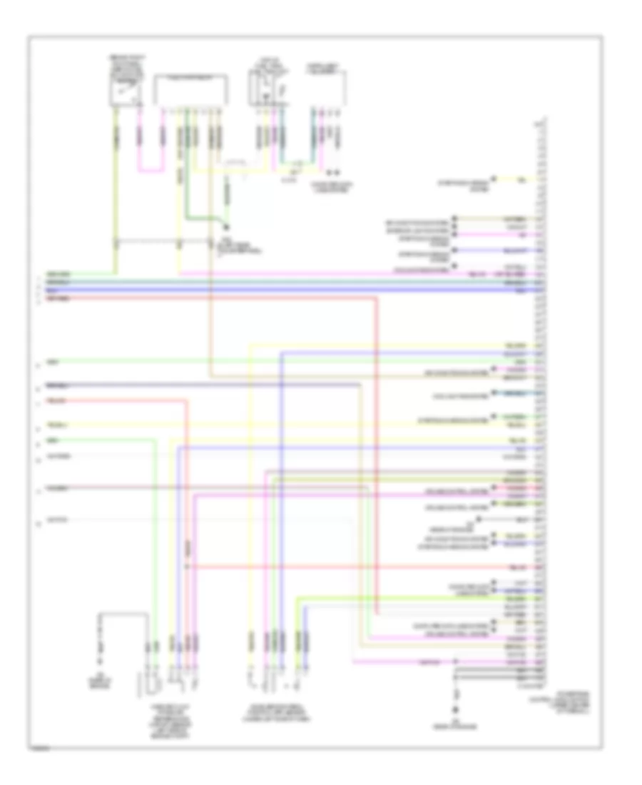
2.5L, Engine Performance Wiring Diagram (4 of 4) for Mazda Tribute i Grand Touring 2011
List of elements for 2.5L, Engine Performance Wiring Diagram (4 of 4) for Mazda Tribute i Grand Touring 2011:
- (behind right kick panel) inertia fuel shutoff (ifs) switch
- (left rear of engine compt) (m/t) clutch cutoff switch
- (left side of dash) (m/t) clutch switch
- (top of fuel tank)
- 0140-175b
- Accelerator pedal position (app) sensor (under left side of dash)
- Air conditioning system
- C-215
- Computer data lines system
- Cooling fans system
- Cruise control system
- Exterior lights system starting/charging system
- Fuel pump relay
- Fuel tank unit
- G11 (left front of engine compt)
- G22 (left rear c-210
- G9 (rear of engine)
- Instrument cluster
- Mass air flow/ intake air temperature (maf/iat) sensor (near rear of cylinder head, in air intake duct)
- Powertrain control module (pcm) (upper center of firewall)
- Quarterpanel)
- Starting/charging system
3.0L
3.0L, Engine Performance Wiring Diagram (1 of 5) for Mazda Tribute i Grand Touring 2011
List of elements for 3.0L, Engine Performance Wiring Diagram (1 of 5) for Mazda Tribute i Grand Touring 2011:
- (top left of engine)
- (top right of engine)
- (top right of engine) fuel injector 1
- 0140-275e
- C-110
- Coil on plug 1 (top right of engine)
- Coil on plug 2 (top right of engine)
- Coil on plug 3 (top right of engine)
- Coil on plug 4 (top left of engine)
- Coil on plug 5 (top left of engine)
- Coil on plug 6 (top left of engine)
- Crankshaft position sensor (front of engine)
- Fuel injector 2
- Fuel injector 3
- Fuel injector 4
- Fuel injector 5
- Fuel injector 6
- Ignition transformer capacitor (on top of engine)
- Powertrain control module (pcm) (upper center of firewall)
3.0L, Engine Performance Wiring Diagram (2 of 5) for Mazda Tribute i Grand Touring 2011
List of elements for 3.0L, Engine Performance Wiring Diagram (2 of 5) for Mazda Tribute i Grand Touring 2011:
- (left rear of engine compt) (m/t) clutch cutoff switch
- (left side of dash) (m/t) clutch switch
- (top of engine) electronic throttle control (etc) motor
- Acc
- C-211
- C-212
- Camshaft position sensor 1 (on front of left cylinder head)
- Camshaft position sensor 2 (on front of right cylinder head)
- Cylinder head temperature (cht) sensor (front center of engine)
- Floor shifter
- G11 (left front of engine compt)
- Hot at all times
- Ignition switch
- Knock sensor 1 (left rear of engine)
- Knock sensor 2 (right rear of engine)
- Manifold absolute pressure (map) sensor (right rear of engine compt)
- Off
- Run
- Start
- Transmission control switch
3.0L, Engine Performance Wiring Diagram (3 of 5) for Mazda Tribute i Grand Touring 2011
List of elements for 3.0L, Engine Performance Wiring Diagram (3 of 5) for Mazda Tribute i Grand Touring 2011:
- (front of engine compt)
- (left front of engine compt)
- (right rear of engine compt)
- Battery junction box (on left side of engine compt)
- C-110
- C-133
- Egr stepper motor (left rear of engine)
- Evaporative emission (evap) canister purge valve (rear of engine compt)
- Fuel injector relay
- Fuel pump diode
- Fuel pump relay
- Fuse 10a
- Fuse 15a
- Fuse 20a
- G11 (left front of engine compt)
- Heated oxygen sensor (ho2s) 11 (right side of engine compt)
- Heated oxygen sensor (ho2s) 12
- Heated oxygen sensor (ho2s) 21
- Heated oxygen sensor (ho2s) 22
- Hot at all times
- Pcm power relay
- Variable camshaft timing (vct) valve 1 (top front of engine)
- Variable camshaft timing (vct) valve 2 (top of engine)
- W/ floor shift
- W/o floor shift
3.0L, Engine Performance Wiring Diagram (4 of 5) for Mazda Tribute i Grand Touring 2011
List of elements for 3.0L, Engine Performance Wiring Diagram (4 of 5) for Mazda Tribute i Grand Touring 2011:
- (rear of engine) heated positive crankcase ventilation (pcv) valve
- (under center of vehicle) evap canister vent control solenoid
- (under left rear of vehicle, above fuel tank) fuel tank pressure transducer sensor
- 0140-231
- 0140-232
- 0140-275t
- C-210
- C-327
- Exterior lights system
- Powertrain control module (pcm) (upper center of firewall)
- Transmission
3.0L, Engine Performance Wiring Diagram (5 of 5) for Mazda Tribute i Grand Touring 2011
List of elements for 3.0L, Engine Performance Wiring Diagram (5 of 5) for Mazda Tribute i Grand Touring 2011:
- (behind right kick panel) inertia fuel shutoff (ifs) switch
- (top of fuel tank) fuel tank unit
- 0140-275b
- Accelerator pedal position (app) sensor (under left side of dash)
- Air conditioning system
- C-215
- Computer data lines system
- Cooling fans system
- Cruise control system
- Exterior lights system
- Fuel pump relay
- G22 (left rear c-210
- G9 (rear of engine)
- Instrument cluster
- Mass air flow/ intake air temperature (maf/iat) sensor (left side of engine compt)
- Powertrain control module (pcm) (upper center of firewall)
- Quarterpanel)
- Starting/charging system