ENGINE PERFORMANCE
3.5L
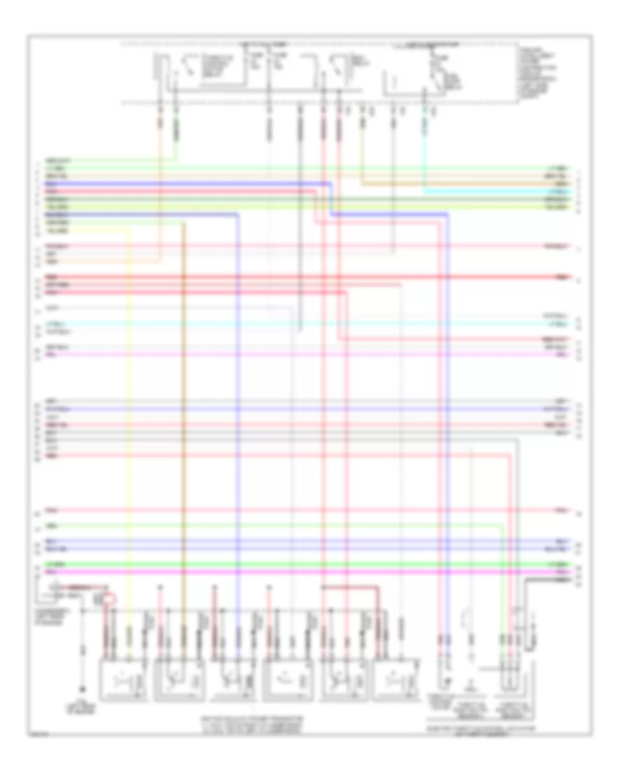
3.5L, Engine Performance Wiring Diagram (1 of 4) for Nissan Maxima S 2010

List of elements for 3.5L, Engine Performance Wiring Diagram (1 of 4) for Nissan Maxima S 2010:
- (1, 3 & 5: top of right cylinder bank) (2, 4 & 6: top of left cylinder bank) fuel injectors
- Af+1
- Af+2
- Af-1
- Af-2
- Afh1
- Afh2
- Avcc1
- Avcc1-cursen,int
- Avcc1-pspres
- Avcc1-tps-b1
- Avcc2
- Battery current sensor
- Cursen
- E18
- E44
- E45
- E46
- E9 (left rear of engine compt)
- Ecm (engine control module) (left front of engine compt)
- Electronic controlled engine mount control solenoid valve
- Emmnv
- Engine coolant temperature sensor (left rear of engine)
- Engine oil temperature sensor (lower right front of engine)
- Enmn1
- Evap
- Evap canister purge volume control solenoid valve (top rear of engine)
- F13
- F14
- Fpr
- Fuse 10a
- Fuse block (j/b) (lower left side of dash)
- Gnd
- Gnda-cursen,int
- Gnda-o2sr1, o2sr2
- Gnda-pdpres
- Gnda-pspres
- Gnda-tps-b1
- Gnda-tw,to1
- Hot in on or start
- Ign 1
- Ign 2
- Ign 3
- Ign 4
- Ign 5
- Ign 6
- Inj 1
- Inj 2
- Inj 3
- Inj 4
- Inj 5
- Inj 6
- Ipdm e/r (intelligent power distribution e201
- Junction block e44 & e45
- Junction block e44 & e46
- Module engine room) (left side of engine compt)
- Motor1-b1
- Motor2-b2
- Motrly-b1
- O2hr1
- O2hr2
- O2sr1
- O2sr2
- Output
- Pdpres
- Pnk
- Power steering pressure sensor (on power steering high pressure tube)
- Pspres
- Pwr
- Qa1-gnda-ta1
- Red
- Refrigerant pressure sensor (on a/c liquid tank)
- Sig
- Ssoff
- Ta1
- To1
- Tps1-b1
- Tps2-b1
- Vias 1
- Vias 2
- Vmot-b1
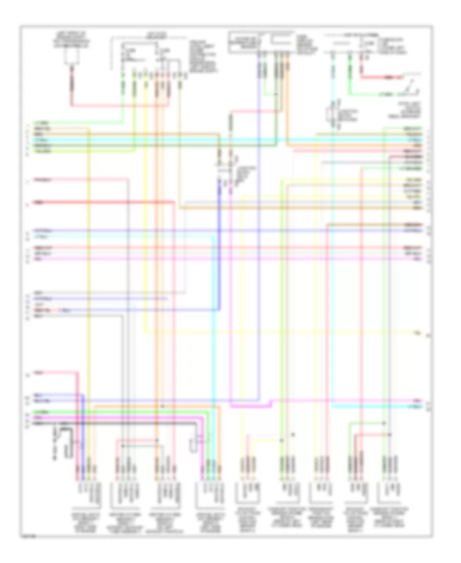
3.5L, Engine Performance Wiring Diagram (2 of 4) for Nissan Maxima S 2010
List of elements for 3.5L, Engine Performance Wiring Diagram (2 of 4) for Nissan Maxima S 2010:
- Condenser 2 (left rear of engine)
- E18
- Ecm relay
- Electric throttle control actuator (on throttle body)
- F10
- F16 (left rear of engine)
- Fuel pump relay
- Fuse 15a
- Hot at all times
- Hot in on or start
- Ignition coils (w/ power transistor) (1, 3 & 5: top of right cylinder bank) (2, 4 & 6: top of left cylinder bank)
- Ipdm e/r (intelligent power distribution module engine room) (left side of engine compt)
- Loop wire
- Nca
- Plug spark
- Pnk
- Red
- Spark plug
- Throttle control motor
- Throttle control motor relay
- Throttle position (tp) sensor 1
- Throttle position (tp) sensor 2
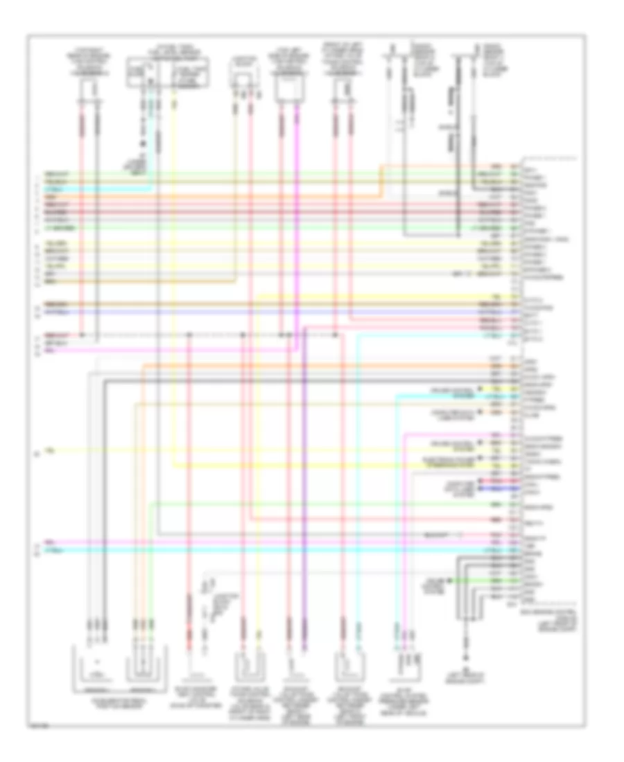
3.5L, Engine Performance Wiring Diagram (3 of 4) for Nissan Maxima S 2010
List of elements for 3.5L, Engine Performance Wiring Diagram (3 of 4) for Nissan Maxima S 2010:
- (left front of engine compt) tcm (transmission control module)
- Af (+)
- Af (-)
- Air/fuel ratio (a/f) sensor 1 (bank 1) (right side of engine)
- Air/fuel ratio (a/f) sensor 1 (bank 2) (left side of engine)
- Avcc1
- Avcc2
- Camshaft position sensor (phase) (bank 1) (rear of right cylinder head)
- Camshaft position sensor (phase) (bank 2) (rear of left cylinder head)
- Crankshaft position sensor (pos) (left rear of engine)
- E18
- E44
- E44 junction block e44 & e45
- E44 junction block e44 & e45 e45
- E45
- Exhaust valve timing control position sensor (bank 1)
- Exhaust valve timing control position sensor (bank 2)
- F10
- Fuse 10a
- Fuse 15a
- Fuse block (j/b) (lower left side of dash)
- Gnd
- Heated oxygen sensor 2 (bank 1) (on right exhaust tube assembly)
- Heated oxygen sensor 2 (bank 2) (on left exhaust manifold)
- Heater (+)
- Heater (-)
- Hot at all times
- Hot in on or start
- Intake air temperature sensor
- Ipdm e/r (intelligent power distribution module engine room) (left side of engine compt)
- Mass airflow sensor (on intake air duct)
- Nca
- Output
- Phase
- Pnk
- Pos
- Pwr
- Red
- Sens (+)
- Sens (-)
- Stop light switch (on brake pedal bracket)
3.5L, Engine Performance Wiring Diagram (4 of 4) for Nissan Maxima S 2010
List of elements for 3.5L, Engine Performance Wiring Diagram (4 of 4) for Nissan Maxima S 2010:
- (front of left cylinder head) intake valve timing control solenoid valve (bank 1)
- (in fuel tank) fuel level sensor unit & fuel pump
- (top left side of engine) vias control solenoid valve (bank 1)
- (top right rear of engine) vias control solenoid valve (bank 2)
- Accelerator pedal position sensor
- Aps1
- Aps2
- Ascdsw
- Avcc1-aps1
- Avcc2-aps2
- Avcc2-ftpres
- Avcc2-pdpres
- Avcc2-pos
- B7 (under driver's seat)
- Batt
- Bncsw
- Brake
- Can-h
- Can-l
- Cdcv
- Computer data lines system
- Cruise control system
- Cvtc 1
- Cvtc 2
- E phase 1
- E-phase 2
- E10
- E45
- E50
- E9 (left rear of engine compt)
- Ecm (engine control module) (left front of engine compt)
- Electronic power steering system
- Evap canister vent control valve (on evap canister)
- Evap control system pressure sensor (under left
- Evtc 1
- Evtc 2
- Exhaust valve timing control magnet retarder (bank 1) (left rear of engine)
- Exhaust valve timing control magnet retarder (bank 2) (left front of engine)
- F13
- Ftpres
- Fuel pump
- Fuel tank temper- ature sensor
- Gnd
- Gnd-pos
- Gnda-aps1
- Gnda-aps2
- Gnda-ascdsw
- Gnda-ftpres
- Gnda-knk1, knk2
- Gnda-tf
- Ignsw
- Intake valve timing control solenoid valve (bank 2) (front of right cylinder head)
- Junction block
- Junction block e44 & e45 e44
- Kline
- Knk
- Knk1
- Knk2
- Knock sensor (bank 1) (top of cylinder block)
- Knock sensor (bank 2) (top of cylinder block)
- Neut-h
- Phase 1
- Phase 2
- Pnk
- Pos
- Ptpres
- Pwr
- Qa1+
- Rear of vehicle)
- Red
- Sensor 1
- Sensor 2
- Shield
- Tacho (cabin)
- Vbr