ENGINE PERFORMANCE
3.5L
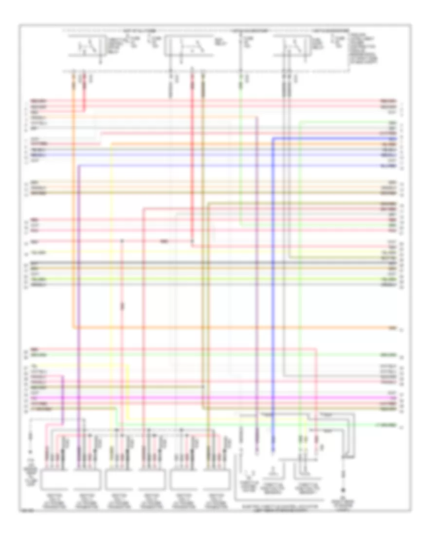
3.5L, Engine Performance Wiring Diagram (1 of 4) for Nissan Quest S 2007

List of elements for 3.5L, Engine Performance Wiring Diagram (1 of 4) for Nissan Quest S 2007:
- (right rear of engine compt)
- 02hr2
- 02sr2
- A/f sns 1
- A/f-h2
- A/f-ip2
- A/f-un1
- A/f-vm1
- A/f-vm2
- Af-h1
- At n sw
- At pn ecm
- At pn sw
- Avcc
- Avcc pdpres
- Avcc2
- C-vtc l
- C-vtc r
- Camshaft position sensor (phase) (bank 1) (top right rear of engine)
- Camshaft position sensor (phase) (bank 2) (left rear of engine)
- Combination meter
- Computer data lines system
- Condenser 1 (left side of engine)
- Crankshaft position sensor (pos) (left rear of engine)
- Ecm (right rear of engine compt)
- Egr volume control valve (right rear of engine)
- Egrts
- Enmn 1
- Enmn 2
- Erg 1
- Erg 2
- Erg 3
- Erg 4
- Evap
- Evap canister purge volume control solenoid valve (right rear of engine)
- F16 (on eng, near oil filler cap)
- Ftprs
- Fuel injector
- Gnd
- Ign 5 sig
- Inj 1 ctrl
- Inj 2 ctrl
- Inj 3 ctrl
- Inj 4 ctrl
- Inj 5 ctrl
- Inj 6 ctrl
- Knk1
- Knock sensor (top of engine)
- Malfunction indicator lamp
- Motor 1
- Motor 2
- Nca
- O2hr1
- Phase lh
- Phase rh
- Pnk
- Pnk/red
- Pos
- Pspres
- Qa+
- Red
- Refrigerant pressure sensor (right front of engine compt)
- Tps 1
- Unified meter control unit
- Vias ctrl sol
- Vmot
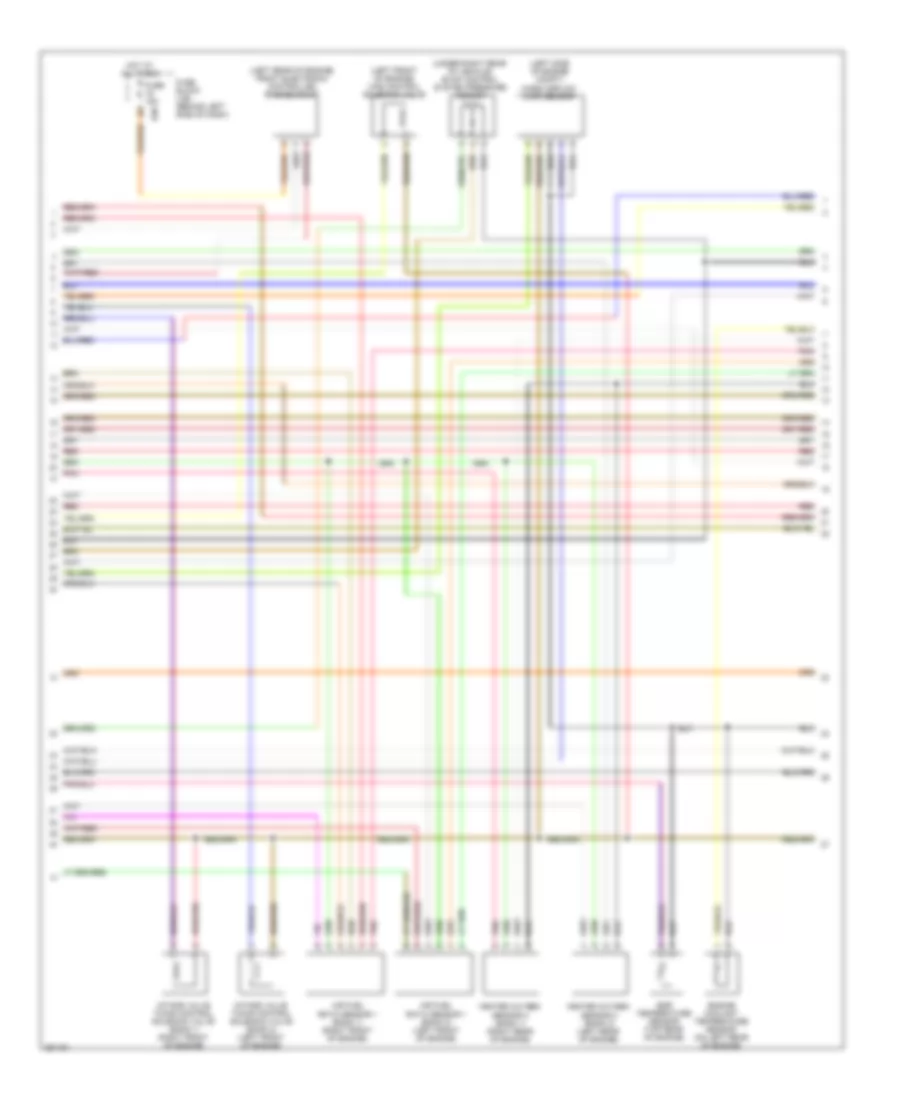
3.5L, Engine Performance Wiring Diagram (2 of 4) for Nissan Quest S 2007
List of elements for 3.5L, Engine Performance Wiring Diagram (2 of 4) for Nissan Quest S 2007:
- (on engine, near oil filler cap)
- E121
- E122
- E124
- E9 (right rear of engine compt)
- Ecm relay
- Electric throttle control actuator (left rear of engine compt)
- F16
- F50
- Fuel pump relay
- Fuse 15a
- Hot at all times
- Hot in on or start
- Ignition coil 1 (w/ power transistor)
- Ignition coil 2 (w/ power transistor)
- Ignition coil 3 (w/ power transistor)
- Ignition coil 4 (w/ power transistor)
- Ignition coil 5 (w/ power transistor)
- Ignition coil 6 (w/ power transistor)
- Ipdm e/r (intelligent power distribution module engine room) (at right side of eng compt)
- Nca
- Pnk
- Red
- Spark plug
- Throttle control motor
- Throttle control motor relay
- Throttle position (tp) sensor 1
- Throttle position (tp) sensor 2
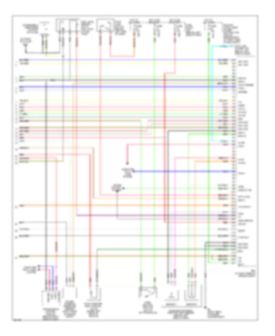
3.5L, Engine Performance Wiring Diagram (3 of 4) for Nissan Quest S 2007
List of elements for 3.5L, Engine Performance Wiring Diagram (3 of 4) for Nissan Quest S 2007:
- (left front of engine) vias control solenoid valve
- (left rear of engine) front electronic controlled engine mount
- (left side of engine compt)
- (under right rear of vehicle) evap control system pressure sensor
- Air fuel ratio sensor 1 (bank 1) (right front of engine)
- Air fuel ratio sensor 1 (bank 2) (left front of engine)
- E30
- Egr temperature sensor (top rear of engine)
- Engine coolant temperature sensor (on left rear of engine)
- Fuse 15a
- Fuse block (j/b) (behind left side of dash)
- Heated oxygen sensor 2 (bank 1) (right rear of engine)
- Heated oxygen sensor 2 (bank 2) (left rear of engine)
- Hot at all times
- Intake valve timing control solenoid valve (bank 1) (right front of engine)
- Intake valve timing control solenoid valve (bank 2) (left front of engine)
- Mass airflow (maf) sensor
- Pnk
- Red
3.5L, Engine Performance Wiring Diagram (4 of 4) for Nissan Quest S 2007
List of elements for 3.5L, Engine Performance Wiring Diagram (4 of 4) for Nissan Quest S 2007:
- (at right "b" pillar) b117
- A/f-ia1
- A/f-ia2
- A/f-un2
- Accelerator pedal position (app) sensor (behind left side of dash)
- Aps1
- Aps2
- Ascd brk sw
- Ascd st sw
- Avcc
- Avcc pspres
- Avcc2
- Batt
- Can h
- Can l
- Can-h
- Can-l
- Cdcv
- Computer data lines system
- Condenser 2 (near base of right "b" pillar)
- Cruise control system
- Data link connector (below left side of dash)
- E124
- E30
- E9 (right rear of engine compartment)
- Ecm (at right rear of engine compt)
- Ecm gnd
- Evap canister vent control valve (under left rear of vehicle)
- F pmp rly
- Fuel level sensor unit & fuel pump (in fuel tank)
- Fuse 10a
- Fuse 15a
- Fuse block (j/b) (behind left side of dash)
- Gnd
- Gnd a
- Gnd a2
- Gnd-a2
- Hot at all times
- Hot in on or start
- Ign 1 sig
- Ign 2 sig
- Ign 3 sig
- Ign 4 sig
- Ign 6 sig
- Ign sw
- Ipdm e/r (intelligent power distribution module engine room) (at right side of eng compt)
- Kline
- Neutl
- O2sr1
- Park/ neutral position switch (on transaxle)
- Pdpres
- Pnk
- Power steering pressure sensor (right rear of engine compt)
- P_n_sw
- Red
- Sen gnd
- Sensor 1
- Sensor 2
- Ssoff
- Stop lamp switch (behind left side of dash)
- Stp lp sw
- Tc mtr rly
- Tps 2
- Transmission control module (behind right side of dash)