HEADLIGHTS
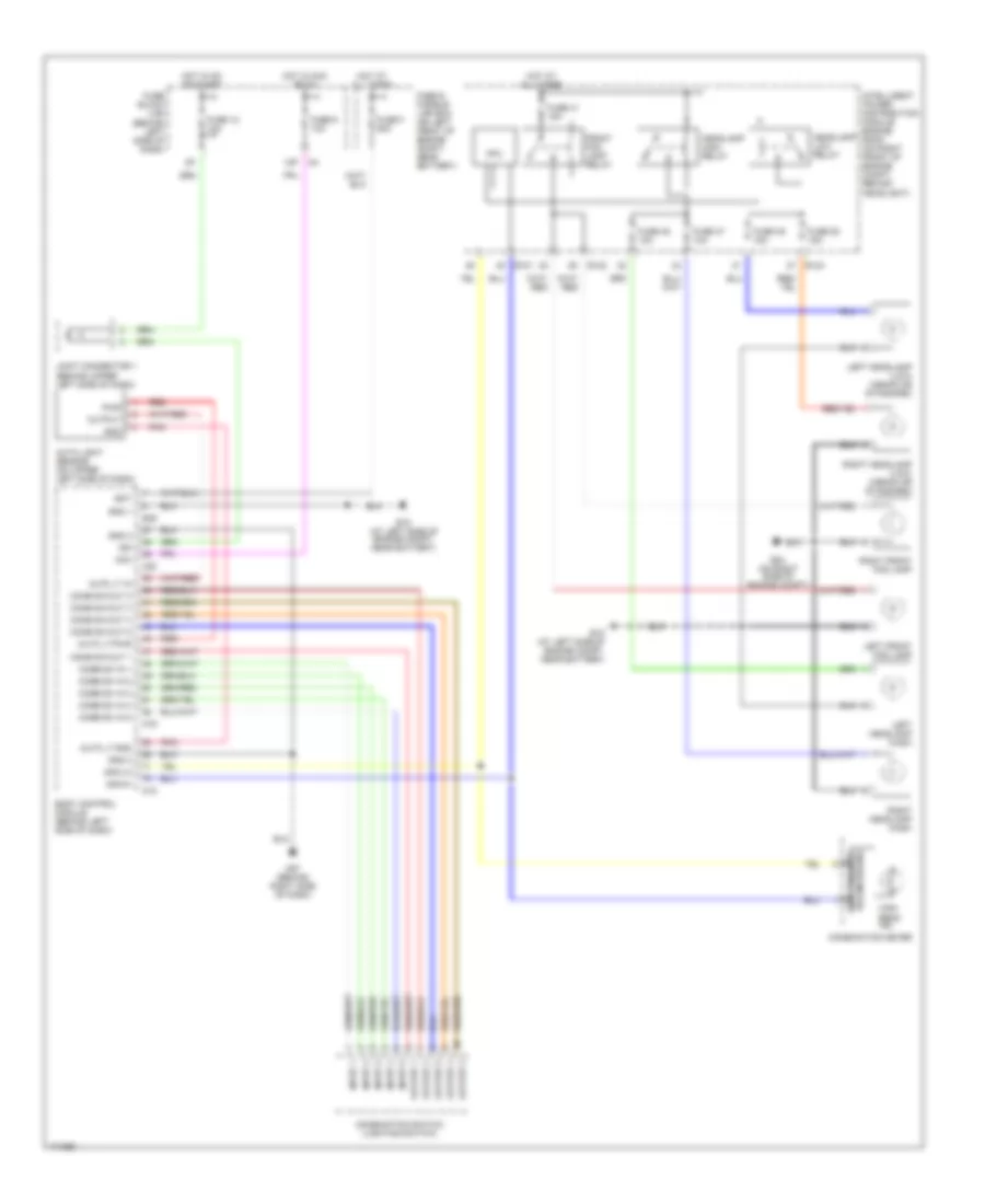
Headlights Wiring Diagram, with DRL for Nissan Altima SE 2003

List of elements for Headlights Wiring Diagram, with DRL for Nissan Altima SE 2003:
- (behind left side of dash)
- 12p
- Acc
- Auto light sensor (on upper left side of dash)
- Auto lt gnd
- Auto lt in
- Auto lt pwr
- Bat
- Body control module (behind left side of dash)
- Can-hi
- Can-lo
- Comb sw in 1
- Comb sw in 2
- Comb sw in 3
- Comb sw in 4
- Comb sw in 5
- Comb sw out 1
- Comb sw out 2
- Comb sw out 3
- Comb sw out 4
- Comb sw out 5
- Combination meter
- Combination switch (lighting switch)
- Cpu
- Daytime light control unit (near right headlight)
- Diode 1 (behind upper left side of dash)
- E102
- E121
- E122
- E124
- E15 (at left side of engine compt, near battery)
- E24 (on right side of engine compt)
- E30
- E39
- Front fog lamp relay
- Fuse & fusible link box (on left front of engine compt, near battery)
- Fuse 12 10a
- Fuse 41 15a
- Fuse 47 10a
- Fuse 48 10a
- Fuse 49 15a
- Fuse 50 15a
- Fuse 6 10a
- Fuse 9 10a
- Fuse block (j/b)
- Fuse f 50a
- Generator
- Gnd
- Gnd 1
- Gnd 2
- Gnd 3
- Headlamp high relay
- Headlamp low relay
- High beam ind
- Hot at all times
- Hot in acc or on
- Hot in on or start
- Hot in start
- Ign
- Input 1
- Input 2
- Input 3
- Input 4
- Input 5
- Intelligent power distribution module engine room (on right front of engine compt, behind headlight)
- Joint connector 1 (behind upper left side of dash)
- Left front fog lamp
- Left headlamp (high)
- Left headlamp (low) (xenon or standard)
- M103
- M104
- M18
- M19
- M20
- M57 (behind right side of dash)
- Output
- Output 1
- Output 2
- Output 3
- Output 4
- Output 5
- Parking brake switch (at base of parking brake lever)
- Pnk
- Pwr
- Red
- Right front fog lamp
- Right headlamp (high)
- Right headlamp (low) (xenon or standard)
- Unified meter control unit
Headlights Wiring Diagram, without DRL for Nissan Altima SE 2003
List of elements for Headlights Wiring Diagram, without DRL for Nissan Altima SE 2003:
- (behind left side of dash)
- 12p
- Acc
- Auto light sensor (on upper left side of dash)
- Auto lt gnd
- Auto lt in
- Auto lt pwr
- Bat
- Body control module (behind left side of dash)
- Can-hi
- Can-lo
- Comb sw in 1
- Comb sw in 2
- Comb sw in 3
- Comb sw in 4
- Comb sw in 5
- Comb sw out 1
- Comb sw out 2
- Comb sw out 3
- Comb sw out 4
- Comb sw out 5
- Combination meter
- Combination switch (lighting switch)
- Cpu
- E121
- E122
- E124
- E15 (at left side of engine compt, near battery)
- E24 (on right side of engine compt)
- E39
- Front fog lamp relay
- Fuse & fusible link box (on left front of engine compt, near battery)
- Fuse 12 10a
- Fuse 41 15a
- Fuse 47 10a
- Fuse 48 10a
- Fuse 49 15a
- Fuse 50 15a
- Fuse 6 10a
- Fuse block (j/b)
- Fuse f 50a
- Gnd
- Gnd 1
- Gnd 2
- Gnd 3
- Headlamp high relay
- Headlamp low relay
- High beam ind
- Hot at all times
- Hot in acc or on
- Hot in on or start
- Ign
- Input 1
- Input 2
- Input 3
- Input 4
- Input 5
- Intelligent power distribution module engine room (on right front of engine compt, behind headlight)
- Joint connector 1 (behind upper left side of dash)
- Left front fog lamp
- Left headlamp (high)
- Left headlamp (low) (xenon or standard)
- M18
- M19
- M20
- M57 (behind right side of dash)
- Output
- Output 1
- Output 2
- Output 3
- Output 4
- Output 5
- Pnk
- Pwr
- Red
- Right front fog lamp
- Right headlamp (high)
- Right headlamp (low) (xenon or standard)
- Unified meter control unit