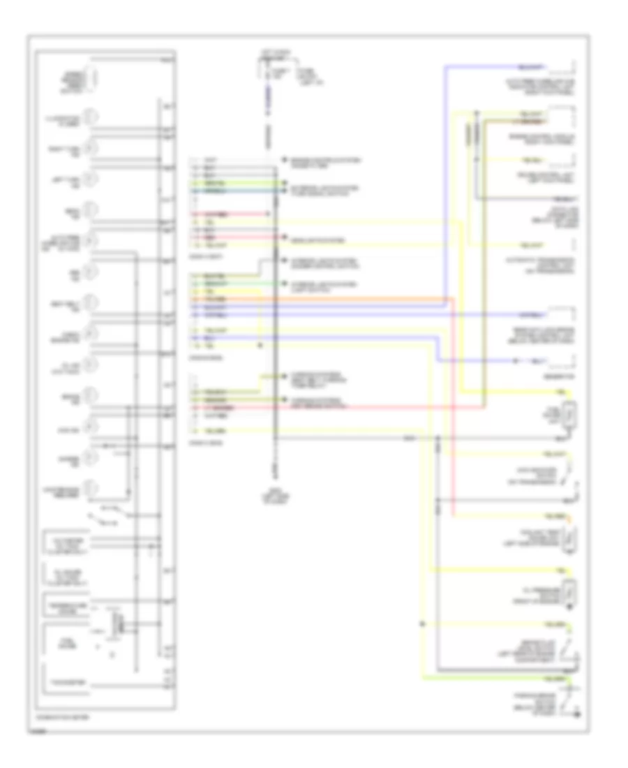
INSTRUMENT CLUSTER
Instrument Cluster Wiring Diagram for Mitsubishi Pickup Mighty Max 1996
List of elements for Instrument Cluster Wiring Diagram for Mitsubishi Pickup Mighty Max 1996:
- (left i/p)
- 4wd ind
- 4wd indicator switch (on transmission)
- A10
- A11
- A12
- Abs ind
- Auto free wheeling hub (w/ 4wd)
- Auto free wheeling hub indicator control unit (right kick panel)
- Automatic transmission control unit (on transmission)
- B10
- Beam ind
- Brake fluid level switch (left rear of engine compartment)
- Brake ind
- Charge ind
- Check engine ind
- Combination meter
- Conn a (b-07)
- Conn b (b-06)
- Conn c (b-05)
- Coolant temp gauge unit (left side of engine)
- Cruise control unit (left kick panel)
- Data link connector (below left side of dash)
- Engine control module (right kick panel)
- Engine controls system (noise filter)
- Exterior lights system (turn signal switch)
- Fuel gauge
- Fuel gauge unit
- Fuse 7 15a
- Fuse block
- G202 (left side of dash)
- Generator
- Headlights system
- Hot in run
- Illumination (5 used)
- Ind
- Interior lights system (dimmer control switch)
- Interior lights system (light switch)
- Left turn ind
- Maintenance required
- Nca
- Oil gauge (w/ tach cluster only)
- Oil ind (w/o tach)
- Oil pressure switch (front of engine)
- Or start
- Parking brake switch (below center of dash)
- Rear anti-lock brake system control unit (below center of dash)
- Red
- Right turn ind
- Seat belt ind
- Speed sensor (reed switch)
- Tachometer
- Temperature gauge
- Voltage limiter
- Voltmeter (w/ tach cluster only)
- Warning systems (key remind switch)
- Warning systems (seat belt warning timer relay)
 English