POWER DOOR LOCKS
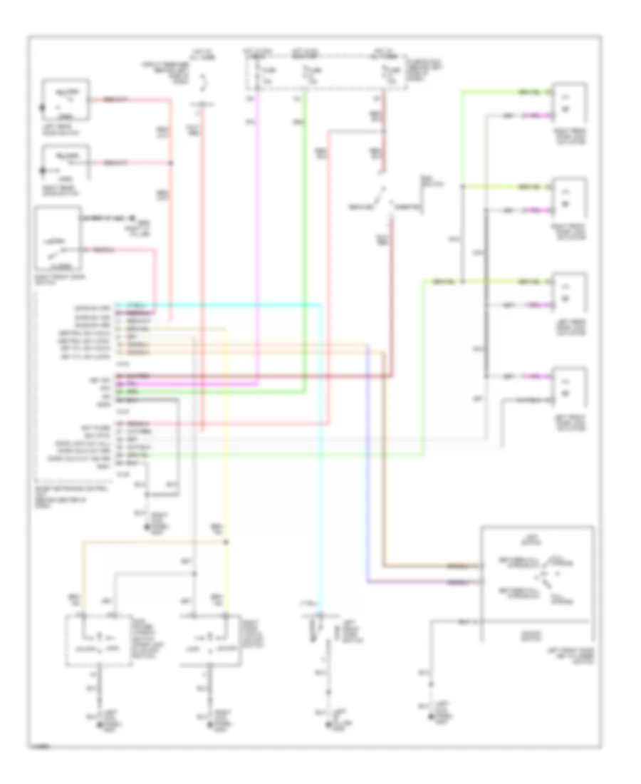
Power Door Lock Wiring Diagram for Nissan Maxima GXE 2001
List of elements for Power Door Lock Wiring Diagram for Nissan Maxima GXE 2001:
- (left "b" pillar) g308
- (left kick panel) g200
- (right kick panel) g203
- 12k
- 12l
- Acc
- Bat (fuse)
- Bat (ptc)
- Between full stroke & n
- Central sw (lock)
- Central sw (unlk)
- Circuit breaker (behind left side of dash)
- Closed
- Door lock out (all)
- Door sw (as)
- Door sw (dr)
- Door sw (rr)
- Door unlk out (as, rr)
- Door unlk out (dr)
- Full stroke
- Fuse 10a
- Fuse block (behind left side of dash)
- G905 (right "c" pillar)
- Gnd1
- Gnd2
- Hot at all times
- Hot in acc or on
- Hot in on or start
- Ign
- Inserted
- Key cyl sw (lock)
- Key cyl sw (unlk)
- Key sw
- Key switch
- Left front door key cylinder switch
- Left front door lock actuator
- Left front door switch
- Left rear door lock actuator
- Left rear door switch
- Lock
- Lock switch
- M143
- M144
- M145
- Main power window switch (door lock & unlock switch)
- Nca
- Open
- Removed
- Right door lock & unlock switch
- Right front door lock actuator
- Right front door switch
- Right rear door lock actuator
- Right rear door switch
- Smart entrance control unit (behind center of dash)
- Unlock
- Unlock switch
 English