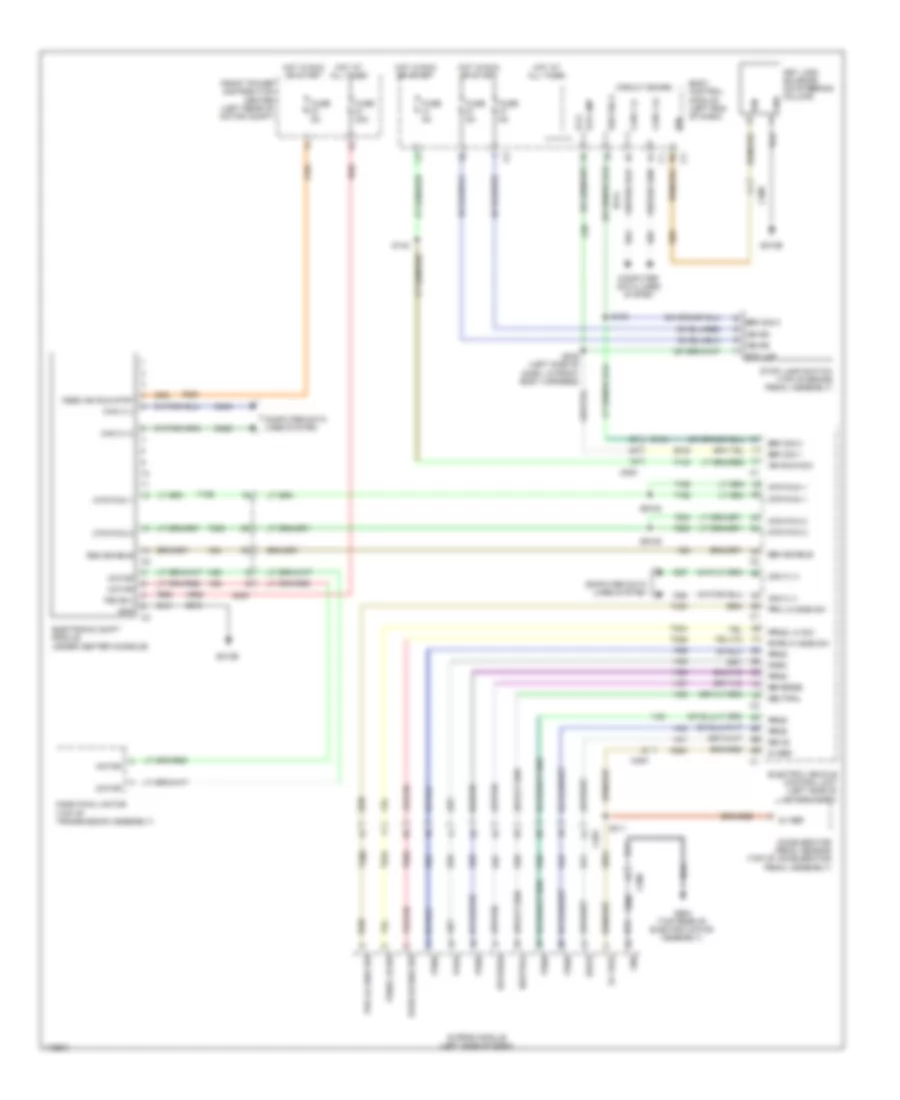
SHIFT INTERLOCK
Shift Interlock Wiring Diagram for Fiat 500e 2013
List of elements for Shift Interlock Wiring Diagram for Fiat 500e 2013:
- 5v ref
- 5v vref
- A988
- Accelerator pedal sensor (top of accelerator pedal assembly)
- B (+)
- B134
- B135
- Body control module (left end of dash)
- Brk sig 1
- Brk sig 2
- C200
- C201
- C308
- Can c (+)
- Can c (-)
- Circuit board
- Computer data lines system
- D27
- D28
- D464
- D465
- D64
- D65
- Drive
- E prnd module (left side of dash)
- Electric vehicle control unit (left side of motor compt)
- Electronic shift module (under center console)
- Esm enable
- F103
- F920
- Front power distribution center (left rear of motor compt)
- Fsd b(+)
- Fsed ign run strt
- Fuse 30a
- Fuse 5a
- G010b
- G68
- G900 (top rear of electric motor assembly)
- Gnd
- H24
- H25
- H26
- H35
- H36
- H37
- H38
- H39
- H40
- H41
- H42
- Hot at all times
- Hot in run or start
- Ign
- Ign rs
- Ign run/acc
- K854
- Key lock solenoid (on steering column)
- L56
- Motor
- Mtr pwm 1
- Mtr pwm 2
- Neutral
- Park
- Park pawl motor (top of transmission assembly)
- Prk lo side sw
- Prnd
- Prndl hi sw
- Red
- Reverse
- Rvrs hi side sw
- S009 (left side of dash, in front body harness)
- S130
- S140
- S311
- S9108
- S9109
- Stop lamp switch (top of brake pedal assembly)
- Stp lmp
- T198
- T200
- T400
- T824
- T826
- Z610
- Z900
 English