SHIFT INTERLOCK
Shift Interlock Wiring Diagram, Evolution for Mitsubishi Lancer DE 2008

List of elements for Shift Interlock Wiring Diagram, Evolution for Mitsubishi Lancer DE 2008:
- (behind left side of dash) g6
- C-304
- C-317
- C-35
- Cpu
- Etacs-ecu (behind left end of dash)
- Fuse 15a
- Fuse 7.5a
- High side switch
- Hot at all times
- Hot in on or start
- Ig1 relay
- Nca
- Red
- Shift lever
- Shift lever position sensor (p)
- Shift lock solenoid
- Stoplight switch (top of brake pedal assembly)
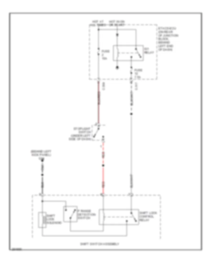
Shift Interlock Wiring Diagram, Except Evolution for Mitsubishi Lancer DE 2008
List of elements for Shift Interlock Wiring Diagram, Except Evolution for Mitsubishi Lancer DE 2008:
- (behind left kick panel) g14
- C-304
- C-317
- Etacs-ecu (on rear of junction block, behind left end of dash)
- Fuse 15a
- Fuse 7.5a
- Hot at all times
- Hot in on or start
- Ig1 relay
- P range detection switch
- Red
- Shift lock control relay
- Shift lock solenoid
- Shift switch assembly
- Stoplight switch (under left side of dash)