STARTING/CHARGING
Charging Wiring Diagram for Mitsubishi Eclipse Spyder GS 2007

List of elements for Charging Wiring Diagram for Mitsubishi Eclipse Spyder GS 2007:
- 120a
- 2.4l
- 3.8l
- 40a
- 7.5a
- Acc
- B22
- Battery
- C202
- C215
- Combination meter
- Engine compartment relay box (left side of engine compt)
- Engine control module (m/t) powertrain control module (a/t) (left side of engine compt, forward of relay box)
- Fuse 13
- Fuse 2 7.5a
- Fusible link 27 (on battery terminal)
- Fusible link 4
- G11 (lower rear of engine)
- G11 (rear of engine)
- G15 (near left front shock tower)
- Generator
- Generator malfunction light ind
- Ignition switch
- Joint connector 2 (behind left side of dash)
- Junction block (under left end of dash)
- Lock
- Power distribution system
- Red
- Run
- Start
- Starting circuit
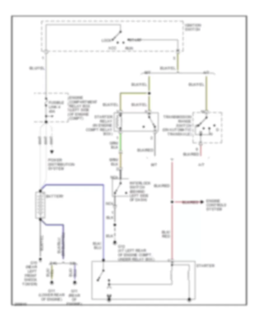
Starting Wiring Diagram for Mitsubishi Eclipse Spyder GS 2007
List of elements for Starting Wiring Diagram for Mitsubishi Eclipse Spyder GS 2007:
- 2.4l
- 3.8l
- A/t
- Acc
- Battery
- Engine compartment relay box (left side of engine compt)
- Engine controls system
- Fusible link 4 40a
- G11 (lower rear of engine)
- G11 (rear of engine)
- G12 (at left rear of engine compt, under relay box)
- G15 (near left front shock tower)
- Ignition switch
- Interlock switch (behind left side of dash)
- Lock
- M/t
- Nca
- Power distribution system
- Run
- Start
- Starter
- Starter relay (in engine compt relay box)
- Transmission range switch (on automatic transaxle)