TRANSMISSION
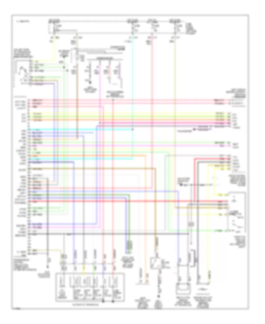
A/T Wiring Diagram for Nissan Altima GLE 2000
List of elements for A/T Wiring Diagram for Nissan Altima GLE 2000:
- (left side of engine compart) dropping resistor
- (on intake manifold) g131
- (on left side of transaxle) park/neutral position switch
- 1 pos
- 1995 vftc c
- 2 pos
- A/t device (o/d switch)
- A/t fluid temp sensor
- Ascd
- Ascd control unit (behind left side of dash)
- Atck
- Automatic transaxle
- Avcc
- Closed throttle
- Clsd sw
- Combination meter
- D pos
- Data in
- Data link connector (behind
- Data out
- Dt1
- Dt2
- Dt3
- Duty sol
- E60 8s
- Eccs control module (ecm) (behind instr panel lower cover)
- Eng rev
- Engine coolant temperature sensor (left side of engine)
- Exterior lights system
- Fl temp
- Fuse 10a
- Fuse 15a
- Fuse block (under left side of dash)
- G131 (on intake manifold)
- G201 (right side of dash)
- Gnd
- Gnd-a
- Hot at all times
- Hot in on or start
- Left side of dash)
- Line press sol valve
- Lu duty
- M17 16n
- M17 8n
- M18 8l
- M20 2k
- Mem b/u
- Nca
- Neut
- O/d off ind
- Obd2
- Od ind
- Od off
- Over- run clutch sol
- Ovr/c
- P/n pos
- Pwr sens
- R pos
- Red
- Revolution sensor (right rear of transaxle)
- Sens gnd
- Shift sol valve a
- Shift sol valve b
- Speedometer
- Ssa
- Ssb
- Tacho
- Tachometer
- Tcc sol valve
- Th/sen
- Throttle position sensor (on throttle body)
- Transmission control module (tcm) (under front of center console)
- Tvo
- Tvo1
- Vehicle speed sensor (on transaxle)
- Vign
- Vsp
- Vsp-1
- Vsp-2
- W/tmp
- Wo sw
- Wot
 English