TRANSMISSION
2.5L
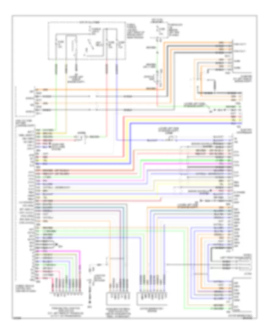
2.5L, A/T Wiring Diagram, Except Hybrid for Nissan Altima Hybrid 2009

List of elements for 2.5L, A/T Wiring Diagram, Except Hybrid for Nissan Altima Hybrid 2009:
- (left front of engine compt) joint connector f02
- (on transmission) park/neutral position (pnp) switch
- 12m m5
- 12p
- A/t check
- At shift dn
- At shift up
- Atf temp sens
- Batt
- Can-h
- Can-l
- Chip select (sel1)
- Clock (sel2)
- Combination meter
- Computer data lines system
- Cvt device
- Cvt fluid temp sensor
- Cvt unit (left side of transmission)
- D range sw
- Data i/o (sel3)
- Down sw
- E10
- E15 (lower left side of engine compt)
- Ecm (left front of engine compt)
- Exterior lights system
- F10
- Fuse 10a
- Fuse block (j/b) (behind left end of dash)
- Gnd
- Hot at all times
- Hot in on or start
- Ign
- Ipdm e/r (intelligent power distribution module engine room) (left side of engine compt)
- J/c f03 (left front of engine compt)
- Joint connector 03 (left front of engine compt)
- K-line
- L range sw
- L/u&select-
- L/u&select-liner sol
- Line pressure solenoid valve
- Lock-up select solenoid valve
- M range
- M61 (behind right end of dash)
- Mode select sw
- N range sw
- Not m range
- On/off sol
- P range sw
- Pl liner sol
- Pnk
- Pri oil press sens
- Pri spd
- Pri speed sens
- Primary pressure sensor
- Primary speed sensor
- R range sw
- Red
- Rom assembly
- S/m-a
- S/m-b
- S/m-c
- S/m-d
- Sec liner sol
- Sec oil press sens
- Sec spd
- Sec speed sens
- Secondary pressure sensor
- Secondary pressure solenoid valve
- Secondary speed sensor (on transaxle)
- Sens gnd
- Sens power source
- Sensor gnd
- Starting/ charging system
- Step motor
- Tcm (left front of engine compt)
- Torque converter clutch solenoid valve
- Unified meter control unit (w/ information display)
- Up sw
- Vign
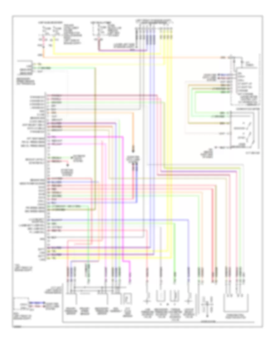
2.5L, A/T Wiring Diagram, Hybrid for Nissan Altima Hybrid 2009
List of elements for 2.5L, A/T Wiring Diagram, Hybrid for Nissan Altima Hybrid 2009:
- (lower left side of engine compt)
- (lower left side of engine compt) j/c e9
- +b2
- +bs
- Accelerator pedal position switch (above accelerator pedal, on bracket)
- Acpb+
- Acpb-
- Batt
- Can h
- Can l
- Cb1
- Cei
- Clk
- Clk+
- Clk-
- Computer data lines system
- Crf
- E12
- E24
- E308
- E309
- E310
- E311
- E313
- E44
- E45
- E46
- E65
- E66
- E69
- E9 (lower left side of engine compt)
- Electric compressor
- Engine controls system
- Eo1
- Eo2
- Ep1 (gnd a1)
- Ep2 (gnd a2)
- Eti
- F250
- F252
- F69
- F77
- F79
- F85
- Fuse & fusible link box (left front of engine compt, near ipdm e/r)
- Fuse 10a
- Fuse block j/b (behind left end of dash)
- Fusible link g 50a
- Gcs
- Gcsg
- Gi (phase)
- Gmt
- Gmtg
- Gnd1
- Gnd2
- Grf
- Grfg
- Gsn
- Gsng
- High volt+
- High volt-
- High voltage battery (luggage compt)
- Hot at all times
- Hot in on or start
- Hsdn
- Htm+
- Htm-
- Hybrid vehicle control ecu (center of dash)
- Igct relay
- Ilk (connsw)
- Ilki
- Inverter (at left side of engine compt)
- Ite
- J/b e44 & e46
- J/c e05
- J/c f08
- Junction block e44 & e45
- Mcs
- Mcsg
- Mg ecu (left front engine compt)
- Mmt
- Mmtg
- Motor generator 1 (engine)
- Motor generator 2 (engine)
- Mrel (ssoft)
- Mrf
- Mrfg
- Msn
- Msng
- Mth+
- Mth-
- Park/neutral position (pnp) switch (m/t: left rear of transaxle) (w/ cvt: on transmission)
- Pnk
- Red
- Req+
- Req-
- Shield
- Stb
- Vb (vbr1)
- Vb2 (vbr2)
- Vc1
- Vc2
- Vcp1 (avcc1)
- Vcp2 (avcc2)
- Vpa (apsi)
- Vpa1
- Vpa2
- Vpa2 (aps2)
3.5L
3.5L, A/T Wiring Diagram for Nissan Altima Hybrid 2009
List of elements for 3.5L, A/T Wiring Diagram for Nissan Altima Hybrid 2009:
- (left front of engine compt) joint connector f05
- (lower left side of engine compt) e15
- 12m m5
- A/t check
- At shift dn
- At shift up
- Atf temp sens
- Backup lmp rly
- Batt
- Can-h
- Can-l
- Chip select (sel1)
- Clock (sel2)
- Combination meter
- Computer data lines system
- Cvt device
- Cvt fluid temp sensor
- Cvt unit (left side of transmission)
- D range sw
- Data i/o (sel3)
- Down sw
- E10
- Ecm (left front of engine compt)
- Exterior lights system
- F10
- Fuse 10a
- Fuse block (j/b) (behind left end of dash)
- Gnd
- Hot at all times
- Hot in on or start
- Ign
- Ipdm e/r (intelligent power distribution module engine room) (left side of engine compt)
- K-line
- L range sw
- L/u & select- on/off sol
- L/u&select-liner sol
- Line pressure solenoid valve
- Lock-up select solenoid valve
- M range
- M61 (behind right end of dash)
- Mode select sw
- N range sw
- Not m range
- P range sw
- Park/neutral position switch
- Pl liner sol
- Pnk
- Pri oil press sens
- Pri speed sens
- Primary pressure sensor
- Primary speed sensor
- R range sw
- Red
- Rom assembly
- S/m-a
- S/m-b
- S/m-c
- S/m-d
- Sec liner sol
- Sec oil press sens
- Sec speed sens
- Secondary pressure sensor
- Secondary pressure solenoid valve
- Secondary speed sensor (on transaxle)
- Sens gnd
- Sens power source
- Sens spd
- Sensor gnd
- Starter rly
- Starting/ charging system
- Step motor
- Tcm (left front of engine compt)
- Torque converter clutch solenoid valve
- Unified meter control unit (w/ information display)
- Up sw
- Vign