TRANSMISSION
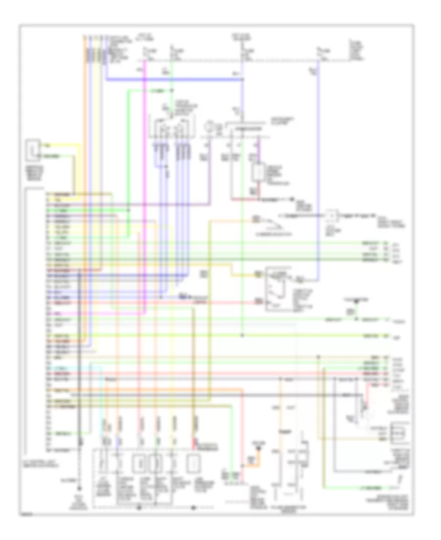
Transmission Wiring Diagram for Nissan Quest GXE 1996
List of elements for Transmission Wiring Diagram for Nissan Quest GXE 1996:
- (top of transaxle) inhibitor switch
- A/t control unit (behind glove box)
- A/t fluid temper- ature sensor
- All times
- Ascd control unit (behind center console)
- Atck
- Automatic transaxle red
- Avcc
- Backup lights
- Closed throttle
- Cruise
- Data link connector (for consult) (below left side of i/p)
- Dropping resistor (rear of engine)
- Dt1
- Dt2
- Dt3
- Eccs control module (behind glove box)
- Engine coolant temperature sensor (right side of engine)
- Fuse 10a
- Fuse block (left kick panel)
- G103 (right front shock tower)
- G131 (on intake manifold)
- G206 (center of dash)
- Gnd-a
- Hot at
- Hot in on or start
- Ind.
- Instrument cluster
- J/c 2 (in fuse box)
- Line pressure solenoid valve
- Nca
- Neut
- O.d. off ind.
- Over- run clutch sol- enoid valve
- Overdrive switch
- Pulse generator sensor
- Red
- Shift sol- enoid valve a
- Shift solenoid valve b
- Speedometer
- Tacho
- Tachometer
- Throttle position sensor (on throttle body)
- Throttle position switch (on throttle body)
- Torque con- verter clutch solenoid valve
- Tvo
- Tvo1
- Vehicle speed sensor (on transaxle)
- Vsp
- W/tmp
- Wot
 English