TRANSMISSION
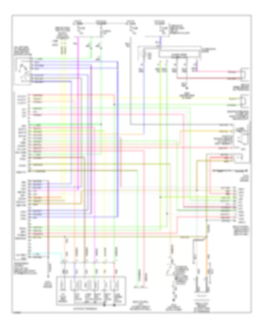
A/T Wiring Diagram for Nissan Quest GXE 2000
List of elements for A/T Wiring Diagram for Nissan Quest GXE 2000:
- (1999)
- (2000)
- (behind dash, next to fuse block) data link connector
- (on left side of transaxle) park/neutral position switch
- 1-sw
- 2-sw
- A/t device (overdrive control switch) (on lower portion of steering column)
- A/t fluid temp sensor
- Acsd 4th
- All times
- Ascd control unit (at right side of driver's footwell)
- Atck
- Automatic transaxle
- Avcc
- Closed throttle
- Combination meter
- Crui acsd
- D-sw
- Data in
- Data out
- Dropping resistor (lower left front corner of engine compt)
- Dt1
- Dt2
- Dt3
- Eccs control module (ecm) (behind right
- Fld temp
- Full sw
- Fuse 10a
- Fuse 30 10a
- Fuse block (behind dash, left of steering column)
- G102 (left front shock tower)
- G134 (top of engine)
- G206 (center rear of dash)
- Gnd
- Gnd-a
- Hot at
- Hot at all times
- Hot in on or start
- Idle sw
- Line press sol valve
- Lu duty
- Mem b/u
- N-sw
- Nca
- Neut
- O/d ind
- O/d off ind
- O/d sw
- Obd2
- Over- run clutch sol
- Ovr/c
- Pl duty
- R-sw
- Red
- Revolution sensor (on right side of transaxle)
- Sen pwr
- Sens gnd
- Shift a
- Shift b
- Shift sol valve a
- Shift sol valve b
- Side of dash)
- Tach
- Tacho
- Tcc sol valve
- Th sens
- Throttle position sensor (on throttle body assembly)
- Transmission control module (tcm) (behind dash, right of steering column)
- Tvo1
- Tvoo
- Unified meter control unit
- Vehicle speed sensor (on transaxle)
- Vign
- Vsp
- Vsp-1
- Vsp-2
- Wot
 English