WARNING SYSTEMS
Warning Systems Wiring Diagram for Mitsubishi Eclipse Spyder GS 2004
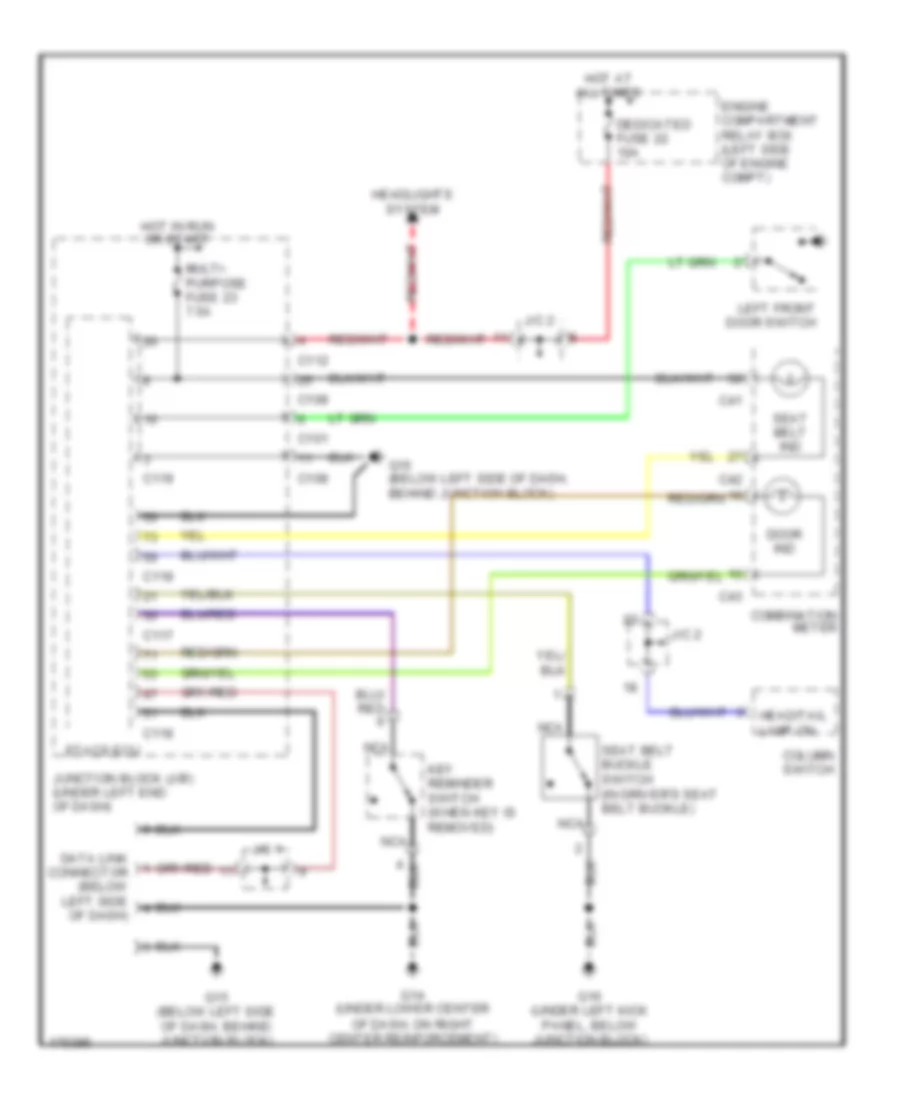
List of elements for Warning Systems Wiring Diagram for Mitsubishi Eclipse Spyder GS 2004:
- C101
- C108
- C112
- C117
- C118
- C119
- C41
- C42
- C43
- Column switch
- Combination meter
- Data link connector (below left side of dash)
- Dedicated fuse 22 10a
- Door ind
- Engine compartment relay box (left side of engine compt)
- Etacs ecu
- G14 (under lower center of dash, on right center reinforcement)
- G15 (below left side of dash, behind junction block)
- G16 (under left kick panel, below junction block)
- Head/tail lamp on
- Headlights system
- Hot at all times
- Hot in run or start
- J/c 1
- J/c 2
- Junction block (j/b) (under left end of dash)
- Key reminder switch (when key is removed)
- Left front door switch
- Multi- purpose fuse 23 7.5a
- Nca
- Seat belt buckle switch (in driver's seat belt buckle)
- Seat belt ind
 English