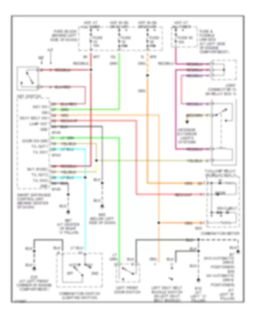
WARNING SYSTEMS
Warning Systems Wiring Diagram for Nissan Maxima SE 2003
List of elements for Warning Systems Wiring Diagram for Nissan Maxima SE 2003:
- (at left "b" pillar)
- 12l
- 1st
- 2nd
- A/t
- Auto
- B12 (at left ``c" pillar)
- B59 (w/ automatic drive
- B7 (w/o automatic drive
- Bat (fuse)
- Combination meter
- Combination switch (lighting switch)
- Door
- Door sw (dr)
- E22 (at left front corner of engine compartment)
- Fuse & fusible link box (at left side of engine compartment)
- Fuse 10a
- Fuse 60 10a
- Fuse block (behind left side of dash)
- Gnd
- Hot at all times
- Hot in on or start
- Ign
- Interior, exterior lights systems
- Joint connector 13 (in relay box 1)
- Key sw
- Key switch
- Lamp out
- Left front door switch
- Left seat belt buckle switch (in left seat belt buckle)
- M/t
- M143
- M144
- M145
- M17
- M19
- M25 (below left side of dash)
- M33
- M87 (at center of right ``a" pillar)
- Off
- Positioner)
- Seat belt
- Seat belt sw
- Smart entrance control unit (behind center of dash)
- T/l out1
- T/l out2
- T/l sw1
- T/l sw2
- Taillamp relay (in relay box 1)
 English