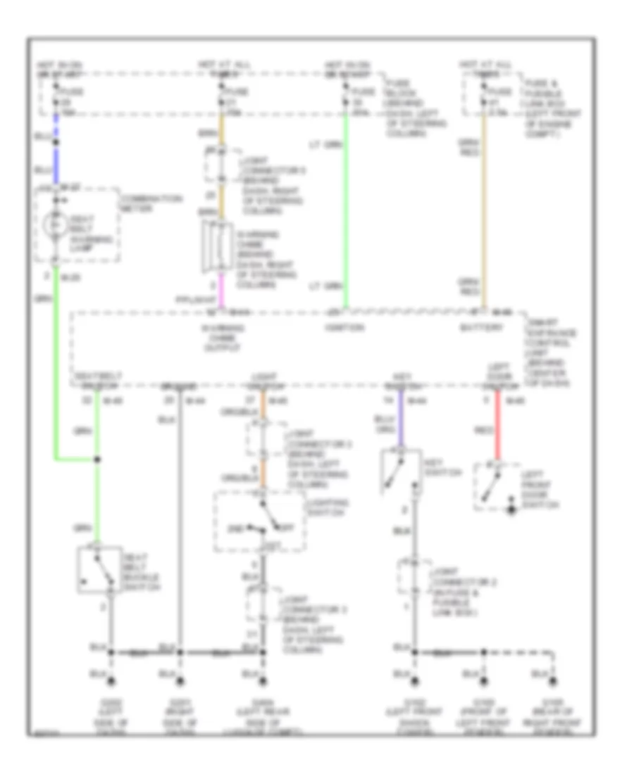
WARNING SYSTEMS
Warning System Wiring Diagrams for Nissan Quest GLE 1998
List of elements for Warning System Wiring Diagrams for Nissan Quest GLE 1998:
- 1st
- 2nd
- Battery
- Combination meter
- Fuse & fusible link box (left front of engine compt)
- Fuse 10a
- Fuse 15a
- Fuse 7.5a
- Fuse block (behind dash, left of steering column)
- G100 (front of left front fender)
- G102 (left front shock tower)
- G105 (rear of right front fender)
- G201 (right side of dash)
- G202 (left side of dash)
- G404 (left rear side of luggage compt)
- Ground
- Hot at all times
- Hot in on or start
- Ignition
- Joint connector 2 (in fuse & fusible link box)
- Joint connector 3 (behind dash, left of steering column)
- Joint connector 5 (behind dash, right of steering column)
- Key switch
- Left door switch
- Left front door switch
- Light switch
- Lighting switch
- M-26
- M-27
- M-44
- M-46
- Off
- Red
- Seat belt buckle switch
- Seat belt warning lamp
- Seatbelt switch
- Smart entrance control unit (behind center of dash)
- Warning chime (behind dash, right of steering column)
- Warning chime output
 English