AIR CONDITIONING
Compressor Wiring Diagram for Chevrolet Camaro SS 2010

List of elements for Compressor Wiring Diagram for Chevrolet Camaro SS 2010:
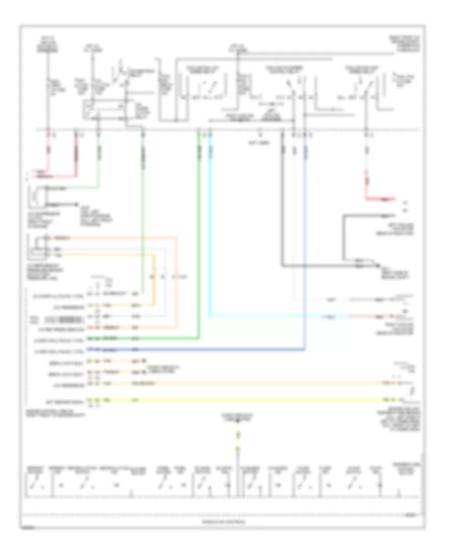
Manual A/C Wiring Diagram (1 of 2) for Chevrolet Camaro SS 2010
List of elements for Manual A/C Wiring Diagram (1 of 2) for Chevrolet Camaro SS 2010:
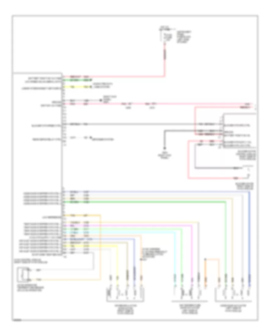
Manual A/C Wiring Diagram (2 of 2) for Chevrolet Camaro SS 2010
List of elements for Manual A/C Wiring Diagram (2 of 2) for Chevrolet Camaro SS 2010: