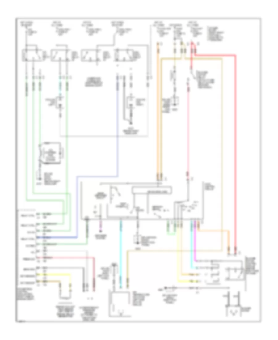
AIR CONDITIONING
Automatic A/C Wiring Diagram for Chevrolet Corvette 2000

List of elements for Automatic A/C Wiring Diagram for Chevrolet Corvette 2000:
- +5v
- A/c clu relay
- A/c compres- sor clutch & didoe
- A/c fuse 24 10a
- A/c on
- A/c refrigerant pressure sensor (attached to the a/c high side line)
- Act pos in
- Air inlet
- All times
- Ambient outside temperature sensor (right front of engine compt)
- Battery
- Blo mot fuse 51 30a
- Blo spd
- Blower motor control module (behind right side of dash)
- C10
- C11
- C12
- C13
- Cool fan 1 fuse 49 30a
- Cool fan 1 relay
- Cool fan 2 fuse 46 30a
- Cool fan 2 relay
- Cool fan 3 fuse 14 10a
- Cool fan 3 relay
- Cooling fans
- D10
- D11
- D12
- D13
- Data line
- Data link connector (dlc) (under dash, below steering column)
- Defrost
- E10
- Ect sensor
- Engine coolant temp sensor (left side of engine, below generator)
- F11
- G107
- G107 (behind right headlamp)
- G203
- Ground
- Heater
- Hot at
- Hot at all times
- Hot in run
- Hvac con fuse 27 10a
- Hvac control module
- Hvac fuse 18 10a
- I/p fuse block (right front footwell, mounted to toe board)
- Ign
- Inside air temperature sensor (in air outlet, right of steering column)
- Inside temp
- Left air temperature actuator (left side of hvac module)
- Mode closed
- Mode open
- Motor drive
- Nca
- Or start
- Outside temp
- Pnk
- Powertrain control module (pcm) (right side of engine compt)
- Press sig
- Red
- Relay ctrl
- Right air temperature actuator (right side of hvac module)
- S201 (dash harn, 35 cm from hvac module)
- S215 (dash harn, 6.5 cm from airbag module breakout)
- Sens gnd
- Sens ground
- Serial data
- Sol 1 ctrl
- Sol 2 ctrl
- Sol 3 ctrl
- Sol 4 ctrl
- Sol 5 ctrl
- Solid state
- Splice pack sp100 (behind right headlamp)
- Splice pack sp202 (right kick panel)
- Star connector 1 (in dash harness)
- Sunload in
- Sunload temperature sensor (top of dash, right side of defroster grille)
- Tan
- Underhood fuse block (right rear of engine compt)
- Vacuum control assembly
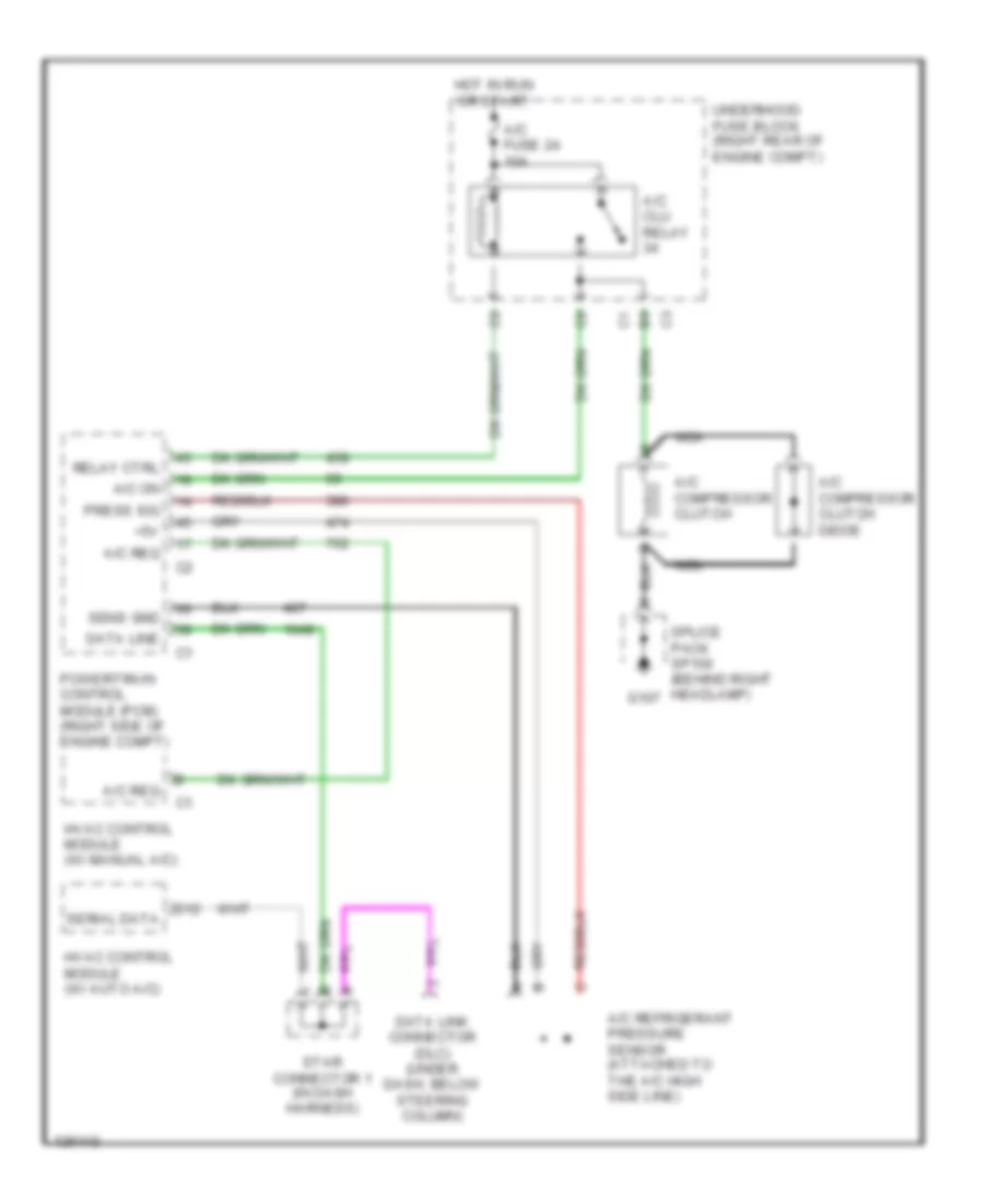
Compressor Wiring Diagram for Chevrolet Corvette 2000
List of elements for Compressor Wiring Diagram for Chevrolet Corvette 2000:
- +5v
- A/c clu relay
- A/c compressor clutch
- A/c compressor clutch didoe
- A/c fuse 24 10a
- A/c on
- A/c refrigerant pressure sensor (attached to the a/c high side line)
- A/c req
- D12
- Data line
- Data link connector (dlc) (under dash, below steering column)
- G107
- Hot in run or start
- Hvac control module (w/ auto a/c)
- Hvac control module (w/ manual a/c)
- Nca
- Powertrain control module (pcm) (right side of engine compt)
- Press sig
- Relay ctrl
- Sens gnd
- Serial data
- Splice pack sp100 (behind right headlamp)
- Star connector 1 (in dash harness)
- Underhood fuse block (right rear of engine compt)
Manual A/C Wiring Diagram for Chevrolet Corvette 2000
List of elements for Manual A/C Wiring Diagram for Chevrolet Corvette 2000:
- +5v
- A/c clu relay
- A/c compres- sor clutch & didoe
- A/c fuse 24 10a
- A/c on
- A/c refrigerant pressure sensor (attached to the a/c high side line)
- A/c req
- Air recirc
- Air source logic
- Air temperature actuator (left side of hvac module)
- All times
- Blo mot maxi fuse 51 30a
- Blower motor
- Blower motor control module (behind right side of dash)
- Blower motor relay (on multi-use relay & fuse bracket, above bcm)
- Cool fan 1 fuse 49 30a
- Cool fan 1 relay
- Cool fan 2 fuse 46 30a
- Cool fan 2 relay
- Cool fan 3 fuse 14 10a
- Cool fan 3 relay
- Cooling fan (left)
- Cooling fan (right)
- D10
- Defogger system
- Defrost/ defog
- E10
- Ect sensor
- Engine coolant temp sensor (left side of engine, below generator)
- F11
- G tan
- G107
- G107 (behind right headlamp)
- G200
- G203
- Hot at
- Hot in run
- Hvac mini fuse 18 10a
- Hvac con mini fuse 27 10a
- Hvac control module
- I/p fuse block (right front footwell, mounted to toe board)
- Nca
- Off
- Or start
- Powertrain control module (pcm) (right side of engine compt)
- Press sig
- Rear defogger circuit
- Red
- Relay ctrl
- Sens gnd
- Splice pack sp100 (behind right headlamp)
- Splice pack sp201 (left kick panel)
- Splice pack sp202 (right kick panel)
- Tan
- Temp control
- Underhood fuse block (right rear of engine compt)