AIR CONDITIONING
Compressor Wiring Diagram for Chevrolet HHR LS 2006

List of elements for Compressor Wiring Diagram for Chevrolet HHR LS 2006:
- (2.4l: right side of engine, near exhaust manifold) (2.2l:top right rear of engine) engine coolant temperature (ect) sensor
- (not used)
- 2.2l
- 2.4l
- 5v ref
- A/c clutch relay
- A/c compressor clutch (lower left front of engine)
- A/c compressor clutch diode
- A/c refrigerant pressure sensor (in right front of engine compt, on a/c line, near compressor)
- A/c req sig
- A/c request indicator
- A/c request sig
- A/c request switch
- Batt
- Body control module (bcm) (under center dash, below radio, on right side of center console)
- C1 d3
- C3 c5
- Computer data lines system
- D12 c1
- Ect sig
- Engine control module (ecm) (left side of engine compt, in front of underhood fuse block)
- F10
- F11 c2
- G109 (on left front shock tower)
- G203 (behind left end of dash)
- Gnd
- Hot at all times
- Hot in run or start
- Hot w/ run/ crank relay energized
- Hvac control assembly
- Hvac/ i/p ign fuse 10a
- Hvac/pk3 fuse 10a
- Ign 1 voltage
- Logic
- Low ref
- Pnk
- Power distribution system
- Press sens sig
- Rly ctrl
- S101 (in forward lamp harness, near left front headlamp, approximately 9 cm from breakout to g109)
- S200 (in i/p harness, near left side of i/p, approximately 29 cm from breakout to g203)
- Serial data
- Serial data +
- Serial data -
- Tan
- Underhood fuse block (in engine compt, next to left strut tower)
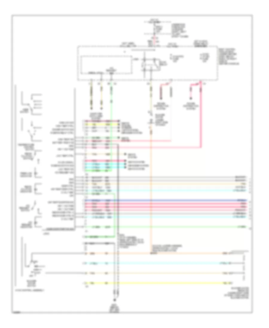
Manual A/C Wiring Diagram (1 of 2) for Chevrolet HHR LS 2006
List of elements for Manual A/C Wiring Diagram (1 of 2) for Chevrolet HHR LS 2006:
- (in hvac jumper harness, approximately 4.9 cm from blower motor) s203
- (not used)
- 5 volt ref
- A/c request indicator
- A/c request sig
- A/c request switch
- Air temp door ctrl
- Air temp door pos sig
- Battery positive
- Bcm 3 fuse 30a
- Blower motor (under right side of dash)
- Blower motor resistor (under right side of dash, forward of blower motor)
- Blower motor switch
- Body control module (bcm) (under center dash, below radio, on right side of center console)
- C2 f6
- Computer data lines system
- Defogger system
- Dimmer switch sig
- Door ctrl
- Fresh air indicator
- G203 (behind left end of dash)
- Gnd
- Hi/low signal
- High
- High temp ctrl
- High temp ind
- High/low sig
- Hot at all times
- Hot w/ run/ crank relay energized
- Hvac control assembly
- Hvac relay
- Hvac/ i/p ign fuse 10a
- Hvac/pk3 fuse 10a
- Ign 1 voltage
- Logic
- Low
- Low temp ctrl
- Low temp ind
- Mode door position sig
- Mode switch
- Off
- Pnk
- Power distribution system
- R defog relay ctrl
- R defog switch sig
- Recir door ctrl a
- Recir door ctrl b
- Recir- culation indicator
- Recir- culation switch
- S200 (in i/p harness, near left side of i/p, approximately 29 cm from breakout to g203)
- Seats system
- Seats system interior lights system
- Serial data
- Tan
- Temperature control switch
- Underhood fuse block (in engine compt, next to left strut tower)
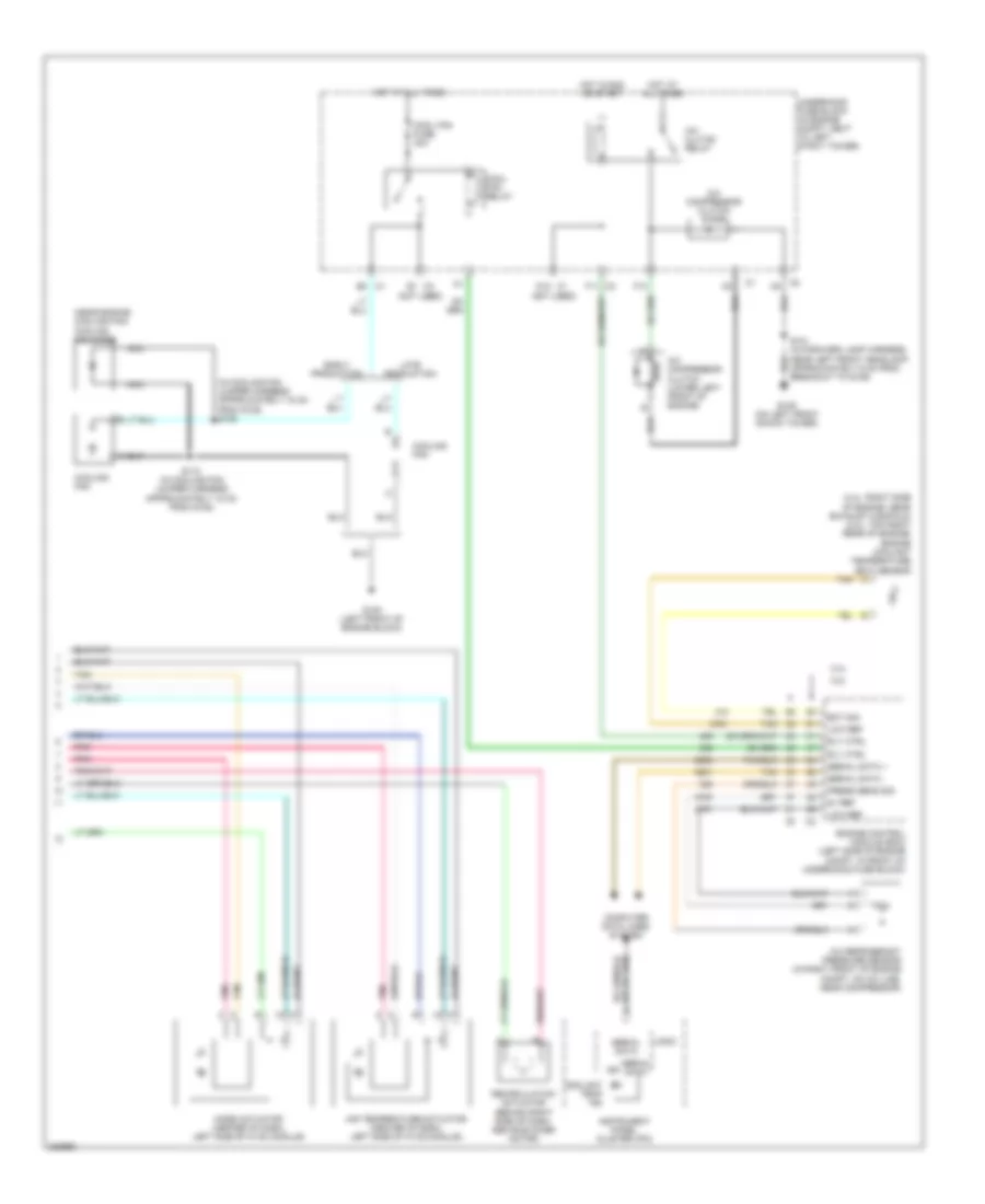
Manual A/C Wiring Diagram (2 of 2) for Chevrolet HHR LS 2006
List of elements for Manual A/C Wiring Diagram (2 of 2) for Chevrolet HHR LS 2006:
- (2.4l: right side of engine, near exhaust manifold) (2.2l: top right rear of engine) engine coolant temperature (ect) sensor
- (in cooling fan jumper harness approximately 15 cm from g105) s109
- (near engine cooling fan) cooling fan diode
- (not used)
- 2.2l
- 2.4l
- 5v ref
- A/c clutch relay
- A/c compressor clutch (lower left front of engine)
- A/c compressor clutch diode
- A/c refrigerant pressure sensor (in right front of engine compt, on a/c line, near compressor)
- Air temperature actuator (center of dash, left side of hvac module)
- C1 b2
- C2 f11
- C3 c5
- Computer data lines system
- Cool fan fuse 30a
- Cool fan relay
- Coolant temp ind
- Cooling fan
- D12 c1
- E1 c3
- Early production
- Ect sig
- Engine control module (ecm) (left side of engine compt, in front of underhood fuse block)
- F10
- G105 (left front of engine block)
- G109 (on left front shock tower)
- Hot at all times
- Hot in run or start
- Ign
- Instrument panel cluster (ipc)
- Late production
- Logic
- Low ref
- Mode actuator (center of dash, left side of hvac module)
- Nca
- Pnk
- Press sens sig
- Recirculation actuator (behind right side of dash, above blower motor)
- Rly ctrl
- S101 (in forward lamp harness, near left front headlamp, approximately 9 cm from breakout to g109)
- S110 (in cooling fan jumper harness approximately 15 cm from g105)
- Serial data
- Serial data +
- Serial data -
- Tan
- Underhood fuse block (in engine compt, next to left strut tower)