AIR CONDITIONING
Compressor Wiring Diagram for Chevrolet Malibu LS 2000

List of elements for Compressor Wiring Diagram for Chevrolet Malibu LS 2000:
- A/c bfc fuse 10a
- A/c compressor clutch
- A/c compressor clutch diode
- A/c compressor clutch relay
- A/c refrigerant pressure sensor (on front of engine compt)
- A/c req
- A/c request input
- Body control module (bcm) (below right side of dash)
- Clutch rly ctrl
- G117 (right rear of engine)
- Heater a/c control assembly
- Hot in run or start
- Left i/p junction block (left end of dash)
- Powertrain control module (pcm) (below left side of dash, near steering column)
- Sensor ground
- Sensor signal
- Serial data cls 2
- Underhood junction block (left side of engine compt)
- Volts
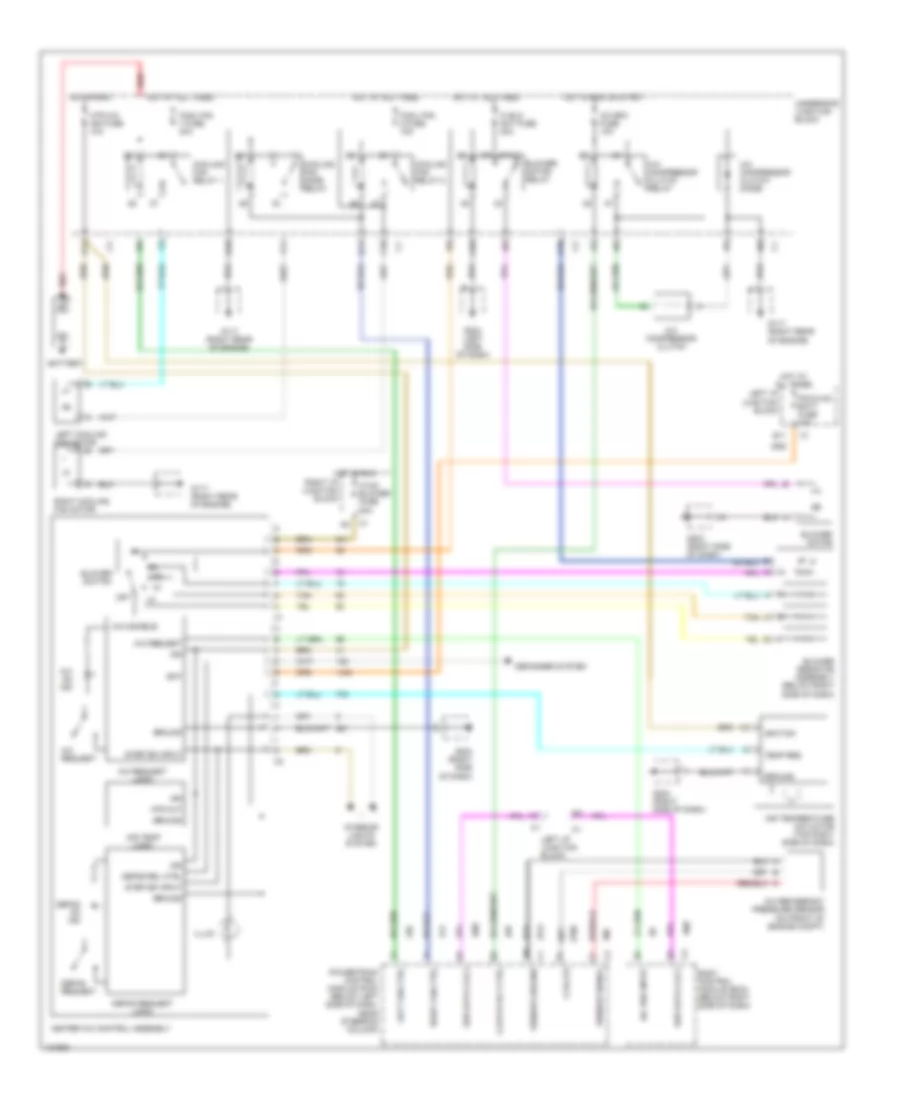
Manual A/C Wiring Diagram for Chevrolet Malibu LS 2000
List of elements for Manual A/C Wiring Diagram for Chevrolet Malibu LS 2000:
- 5 volts
- 87a
- A/c bfc fuse 10a
- A/c compressor clutch
- A/c compressor clutch diode
- A/c compressor clutch relay
- A/c disable
- A/c on ind
- A/c refigerant pressure sensor (on front of engine compt)
- A/c req input
- A/c request
- A/c request logic
- A10
- A11
- Air temp logic
- Air temperature actuator (top right side of dash)
- B11
- Bat
- Battery
- Blower motor
- Blower motor relay
- Blower resistor assembly (below right side of dash)
- Blower switch
- Body control module (bcm) (below right side of dash)
- C10
- Clutch rly ctrl
- Cool fan 1 fuse 30a
- Cool fan 2 fuse 15a
- Cooling fan relay 1
- Cooling fan relay 2
- Cooling fan mode relay
- D10
- D11
- Defog on ind
- Defog rel ctrl
- Defog request
- Defog request logic
- Defogger system
- F11
- G117 (right rear of engine)
- G203 (right side of dash)
- G204 (left side of dash)
- G204 (right side of dash)
- Ground
- Heater a/c control assembly
- Hi blo mot fuse 30a
- Hot at all times
- Hot in run
- Hot in run or start
- Htr a/c ign fuse 10a
- Htr out
- Hvac blower fuse 20a
- Ign
- Ignition
- Illum
- Interior lights system
- Ipc/hvac batt fuse 10a
- Left cooling fan motor
- Left fan ctrl
- Left i/p junction block
- Off
- Powertrain control module (pcm) (below left side of dash, near steering column)
- Red
- Right cooling fan motor
- Right fan ctrl
- Right i/p junction block
- Sensor ground
- Sensor signal
- Ser data cls 2
- Step dim input
- Tan
- Temp req
- Underhood junction block