AIR CONDITIONING
Compressor Wiring Diagram for Chevrolet Malibu LS 2002

List of elements for Compressor Wiring Diagram for Chevrolet Malibu LS 2002:
- A/c bfc fuse 37 10a
- A/c comp micro- relay
- A/c compressor clutch
- A/c compressor clutch diode
- A/c refrigerant pressure sensor (on front of engine compt)
- A/c req
- A/c request sig
- Body control module (bcm) (below right side of dash)
- Class 2 serial data
- Clutch rly ctrl
- G103 (right rear of engine)
- Hot in run or start
- Hvac control assembly
- Left i/p fuse block (left end of dash)
- Low ref
- Powertrain control module (pcm) (below left side of dash, near steering column)
- Sensor signal
- Splice pack sp103
- Underhood fuse block (left side of engine compt)
- Volt ref
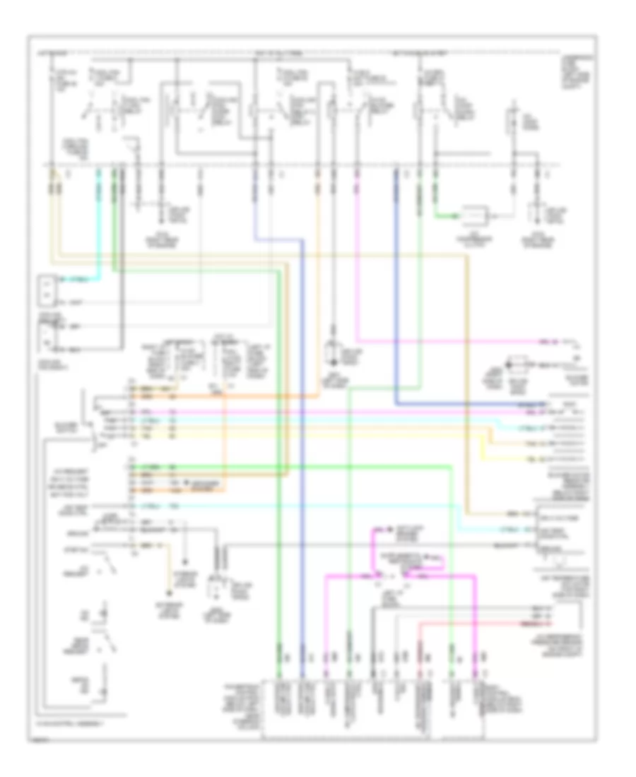
Manual A/C Wiring Diagram for Chevrolet Malibu LS 2002
List of elements for Manual A/C Wiring Diagram for Chevrolet Malibu LS 2002:
- 5 volt ref
- A/c bfc fuse 37 10a
- A/c comp diode
- A/c comp micro- relay
- A/c compressor clutch
- A/c refrigerant pressure sensor (on front of engine compt)
- A/c refrigerant pressure sensor signal
- A/c request
- A10
- A11
- Air temp door ctrl
- Air temperature actuator (top right side of dash)
- Anti-lock brakes system
- B11
- B12
- Bat pos volt
- Blower motor
- Blower motor resistor assembly (below right side of dash)
- Blower switch
- Body control module (bcm) (below right side of dash)
- C10
- C12
- Class 2 serial data
- Cool fan 1 fuse 8 30a
- Cool fan 1 mini- relay
- Cool fan 2 fuse 52 15a
- Cool fan 2 ground fuse 55 15a
- Cooling fan relay 2 mini- relay
- Cooling fan (left)
- Cooling fan (right)
- Cooling fan mode mini- relay
- Ctrl clutch relay a/c compressor
- D10
- D11
- Defog on ind
- Defogger system
- Exterior lights system
- F11
- G103 (right rear of engine)
- G201 (left side of dash)
- G202 (left side of dash)
- G203 (right side of dash)
- Ground
- Hi blo mot fuse 53 30a
- High speed cooling fan relay ctrl
- Hot at all times
- Hot in run
- Hot in run or start
- Htr a/c ign fuse 46 10a
- Hvac blower fuse c 20a
- Hvac blower relay
- Hvac control assembly
- Ign 3 voltage
- Illum
- Interior lights system
- Ipc/ hvac batt fuse 10a
- Left i/p fuse block
- Left i/p fuse block (left end of dash)
- Low reference
- Low speed cooling fan relay ctrl
- Off
- On ind
- Powertrain control module (pcm) (below left side of dash, near steering column)
- Rear defog request
- Right i/p fuse block (right end of dash)
- Rr defog ctrl
- Serial data class 2
- Signal a/c request
- Splice pack sp103
- Splice pack sp201
- Splice pack sp202
- Splice pack sp203
- Step dim
- Tan
- Underhood fuse block (left side of engine compt)