AIR CONDITIONING
Compressor Wiring Diagram for Chevrolet Prizm 2001

List of elements for Compressor Wiring Diagram for Chevrolet Prizm 2001:
- (behind center of dash) junction block 3
- (left front of engine compt)
- (right front of engine) a/c compressor clutch
- (w/ 4 a/t)
- (w/o 4 a/t)
- A/c compressor control module (right side of dash)
- A/c fuse 7.5a
- A/c mg relay
- A/c switch
- Block 2
- Blower speed selector switch
- Dual pressure switch
- Function alarm module (behind left side of dash)
- Fuse & relay
- Fuse & relay block 1 (left front c6 of engine compt)
- Fuse & relay block 1 (left front of engine compt)
- Fuse & relay block 3 (right front of engine)
- G100 (front left fender)
- G101 (right front of engine compt)
- G203 (right kick panel)
- G206 (on left dash support bracket)
- Gauge fuse 10a
- Hot at all times
- Hot in run or start
- Htr fuse 50a
- Htr relay
- Junction block 2 (behind left side of dash)
- Multi-
- Off
- Powertrain control module (pcm) (front of center console)
- Refrigerant pressure switch (right side of engine compt)
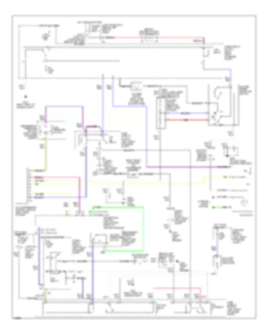
Manual A/C Wiring Diagram for Chevrolet Prizm 2001
List of elements for Manual A/C Wiring Diagram for Chevrolet Prizm 2001:
- (behind center of dash) junction block 3
- (behind left side of dash) sp254
- (left front of engine compt)
- (left side of dash)
- (right front of engine) a/c compressor clutch
- (w/ 4 a/t)
- (w/o 4 a/t)
- A/c comprressor control module (right side of dash)
- A/c fan
- A/c fan relay
- A/c fuse 7.5a
- A/c high pressure switch
- A/c mg relay
- A/c switch
- Auxiliary radiator fan motor
- Block 2
- Blower motor (right side of dash, on blower case)
- Blower motor resistor (right side of dash)
- Blower speed selector switch
- Cds fuse 30a
- Dual pressure switch
- Ecu-ig fuse 10a
- Fan relay 1
- Function alarm module (behind left side of dash)
- Fuse & relay
- Fuse & relay block 1 (left front c6 of engine compt)
- Fuse & relay block 1 (left front of engine compt)
- Fuse & relay block 2
- Fuse & relay block 3 (right front of engine compt)
- Fuse and relay block 2
- G100 (front left fender)
- G101 (right front of engine compt)
- G203 (right kick panel)
- G206 (on left dash support bracket)
- Gauge fuse 10a
- Hot at all times
- Hot in run or start
- Htr fuse 50a
- Htr relay
- Interior lights system
- Junction block 2 (behind left side of dash)
- Junction block 3 (behind center of dash)
- Junction c1
- Main radiator fan motor
- Multi-
- Off
- Powertrain control module (pcm) (front of center console)
- Rdi fuse 30a
- Red
- Refrigerant pressure switch (right side of engine compt)
- Refrigerant pressure switch (right side of engine compt)
- Relay
- S200 (cowl harn, near blower motor res breakout)