AIR CONDITIONING
Compressor Wiring Diagram for Chevrolet SSR 2006

List of elements for Compressor Wiring Diagram for Chevrolet SSR 2006:
- (or 2288)
- 5v ref
- A/c compressor clutch (on a/c compressor)
- A/c fuse 30 10a
- A/c refrigerant pressure sensor (on high pressure hose connection to compressor)
- A/c relay
- A/c req sig
- C1 f3
- Cl rly ctrl
- Computer data lines system
- D11
- Defrost
- Engine control module (ecm) (left front side of engine compt)
- Evaporator temperature sensor (behind radio on top of hvac case)
- Flr
- Flr/defrost
- G100 (lower left front of engine)
- G200
- Hot at all times
- Hot in run or start
- Hvac control module
- Ign e fuse 23 10a
- Logic
- Low ref
- Max defrost
- Mode switch
- Panel
- Panel/flr
- Roof/door module (rear center of passenger compt)
- S207 (i/p harness, 9 cm from hvac control module breakout)
- Sens sig
- Serial data
- Sp200 (right of instrument cluster)
- Underhood fuse block (on left side of engine compt)
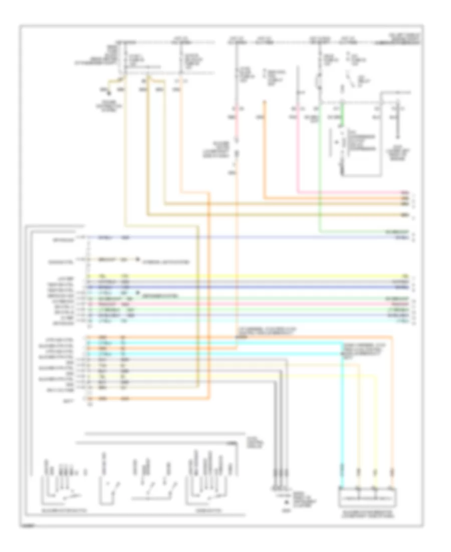
Manual A/C Wiring Diagram (1 of 2) for Chevrolet SSR 2006
List of elements for Manual A/C Wiring Diagram (1 of 2) for Chevrolet SSR 2006:
- (dash harness, 15 cm from hvac control module breakout) s213
- (i/p harness, 15 cm from hvac control module breakout) s209
- (on left side of engine compt) underhood fuse block
- 5v ref
- A/c compressor clutch (on a/c compressor)
- A/c fuse 30 10a
- A/c relay
- A/c req sig
- B c6
- Batt
- Blower motor (lower right side of dash)
- Blower motor resistor (lower right side of dash)
- Blower motor switch
- Blower mtr ctrl
- C1 c1
- C1 f3
- C4 b2
- D11
- Defog sw sig
- Defogger system
- Defrost
- Defrost rear
- Dimming ctrl
- Dr ctrl a
- Dr ctrl b
- Dr pos sig
- Eng cool fan fuse 37 60a
- Flr
- Flr/defrost
- G100 (lower left front of engine)
- G200
- Gnd
- High
- Hot at all times
- Hot in run
- Hot in run or start
- Hvac 1 fuse 39 10a
- Hvac b dd unlck fuse 36 10a
- Hvac blwr fuse 40 40a
- Hvac control module
- Ign 3 voltage
- Ign e fuse 23 10a
- Interior lights system
- Logic
- Low a/c ref
- Low ref
- Max defrost
- Med 1
- Med 2
- Med 3
- Mode switch
- Mtr high ctrl
- Off
- Panel
- Panel/flr
- Pnk
- Power distribution system
- Rear fuse block (rear center of passenger compt)
- Recirc
- Red
- Sp200 (right of instrument cluster)
- Tan
- Temp dr ctrl
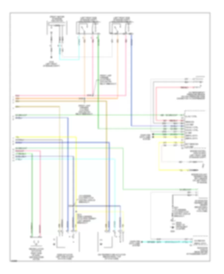
Manual A/C Wiring Diagram (2 of 2) for Chevrolet SSR 2006
List of elements for Manual A/C Wiring Diagram (2 of 2) for Chevrolet SSR 2006:
- (front center of engine) cooling fan
- (front lamp harness, 2.5 cm from cooling fan relay breakout)
- (front lamp harness, 5 cm from cooling fan relay breakout)
- (i/p harness, 5 cm from hvac control module breakout)
- (left front side of engine compt) cooling fan 1 relay
- (left front side of engine compt) cooling fan 2 relay
- (or 2288)
- 5v ref
- A/c refrigerant pressure sensor (on high pressure hose connection to compressor)
- A/c req sig
- Air temperature actuator (behind radio, top of hvac case)
- Cl rly ctrl
- Computer data lines system
- Ect sens sig
- Engine control module (ecm) (left front side of engine compt)
- Engine coolant temperature (ect) sensor (on left front of engine)
- Evaporator temperature sensor (behind radio on top of hvac case)
- Fan rly ctrl
- G105 (left front of engine compt)
- G200
- Logic
- Low ref
- Mode actuator (left side of dash on hvac case)
- Nca
- Pnk
- Recirculation actuator (right side of dash, above blower motor)
- Roof/door module (rear center of passenger compt)
- S105
- S106
- S207 (i/p harness, 9 cm from hvac control module breakout)
- S208
- S212 (dash harness, 2.5 cm from ambient light sensor breakout)
- Sens sig
- Serial data
- Sp200 (right of instrument cluster)