AIR CONDITIONING
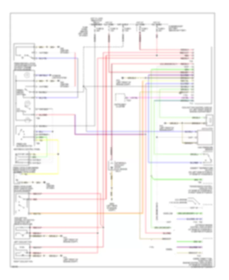
Manual A/C Wiring Diagram for Volkswagen Golf GL 2002
List of elements for Manual A/C Wiring Diagram for Volkswagen Golf GL 2002:
- (1.8l & 2.8l engine)
- (1.9l)
- (2.0l engine)
- (2.8l engine only)
- A/c clutch
- A/c switch
- After-run coolant pump (2.8l engine only)
- Ambient temperature switch (on left side of plenum, at base of windshield)
- Coolant fan control (fc) switch (on bottom left rear of radiator)
- Coolant fan control module (at left front side of engine compartment)
- Diesel
- Diesel direct fuel injection (dfi) engine control module (ecm) (at base of windshield in center of plenum)
- Fresh air blower (right side of dash, on hvac housing)
- Fresh air blower series resistance with fuse (on fresh air blower)
- Fresh air blower switch
- Fresh/ recirc switch
- Fresh/recirculating air door servo motor (on right corner of hvac housing)
- Fuse 16 10a
- Fuse 25 25a
- Fuse 3 40a
- Fuse 5 7.5a
- Fuse 8 30a
- Fuse panel (behind left side of dash)
- Fuse/bracket battery (behind battery)
- G12 (left front of engine compt)
- G45 (center of dash)
- G608 (left rear of engine compt)
- Gasoline
- Heater-a/c control panel
- High pressure sensor
- Hot at all times
- Hot in run
- Hot w/ load reduction relay energized
- Instrument cluster
- Interior lights system
- Left coolant fan
- Motronic engine control module (ecm) (at base of windshield, in center of plenum)
- Red
- Right coolant fan
- T121
- T14
- T32a
- T4a
- T68
- T6d
- T80
- T8b
- Transmission control module (tcm) (at base of windshield, in right side of plenum)
 English