ANTI-LOCK BRAKES
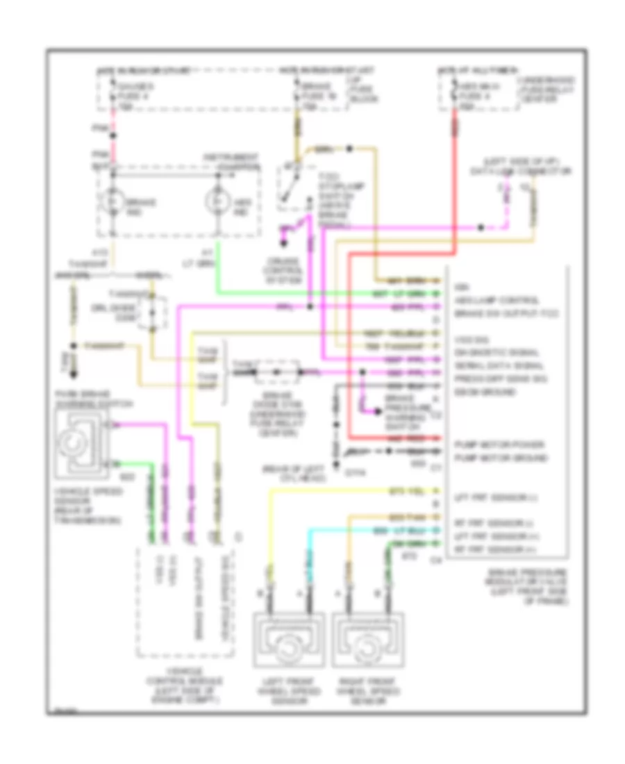
Anti-lock Brake Wiring Diagrams for Chevrolet Astro 1996
List of elements for Anti-lock Brake Wiring Diagrams for Chevrolet Astro 1996:
- (left side of i/p) data link connector
- (rear of left cyl head)
- A13
- Abs ind
- Abs lamp control
- Abs maxi fuse 4 60a
- B17
- Brake diode d100 (underhood fuse-relay center)
- Brake fuse 18 10a
- Brake ind
- Brake pressure modulator valve (left front side of frame)
- Brake pressure warning switch
- Brake sw output
- Brake sw output-tcc
- Cruise control system
- Diagnostic signal
- Drl diode d200
- Ebcm ground
- G114
- Gauges fuse 4 10a
- Hot at all times
- Hot in run or start
- I/p fuse block
- Ign
- Instrument cluster
- Left front wheel speed sensor
- Lft frt sensor (+)
- Lft frt sensor (-)
- Nca
- Park brake warning switch
- Pnk
- Press diff sens sig
- Pump motor ground
- Pump motor power
- Red
- Right front wheel speed sensor
- Rt frt sensor (+)
- Rt frt sensor (-)
- Serial data signal
- Tan
- Tcc/ stoplamp switch (above brake pedal)
- Underhood fuse-relay center
- Vehicle control module (left side of engine compt)
- Vehicle speed sensor (rear of transmission)
- Vehicle speed sig
- Vss (+)
- Vss (-)
- Vss sig
- W/drl
- W/o drl
 English