ANTI-LOCK BRAKES
Anti-Lock Brakes Wiring Diagram for Chevrolet Cab & Chassis Silverado 3500 2007

List of elements for Anti-Lock Brakes Wiring Diagram for Chevrolet Cab & Chassis Silverado 3500 2007:
- (diesel)
- (gas)
- (gas: left rear of eng block) (diesel: right front of eng block)
- (in i/p harness) sp205
- 3.6k ohms
- A10
- Abs fuse 60a
- Abs ind
- Allison
- B10
- Brake fluid level sw in
- Brake fluid level switch (on left side of brake fluid reservoir)
- Brake fuse 10a
- Brake ind
- Brake input
- C12
- C2 b7
- C5 c1
- C9 a
- Clutch start switch (m/t) (top of clutch clutch assy)
- Cpp sw sig
- Data link connector (dlc) (below steering column)
- Del torque sig
- Electronic brake control module (ebcm) (on left side of inner frame)
- Except allison
- Except seo
- Front axle act/sw input
- G104
- G110 (left front body mount)
- G203 (near left "a" pillar)
- Hot at all times
- Hot in run
- Hot in run or start
- I/p fuse block (on lower left side of dash)
- Ign e fuse 10a
- Ignition
- Instrument planel cluster
- Interior lights system
- Left front sensor (+)
- Left front sensor (-)
- Left front wheel speed sensor
- Logic
- Nca
- Pnk
- Powertrain or engine control module (pcm or ecm) (on left front of eng compt)
- Red
- Req torque sig
- Right front sensor (+)
- Right front sensor (-)
- Right front wheel speed sensor
- S102
- S213
- Seo
- Seo ign fuse 10a
- Serial data
- Stoplamp switch (on top of brake pedal bracket)
- Tan
- Tcc brake sw
- Traction control ind (if equipped)
- Traction control switch (if equipped)
- Transfer case shift control module (behind headlamp switch)
- Transmission control module (tcm) (left front of eng compt)
- Transmissions system (allison)
- Transmissions system (transfer case circuit)
- Underhood fuse block (at left side of engine compt)
- Vehicle speed sensor (vss) (nv 4500: left side of transmission, nvg 261-np2: left side of transfer case, nvg 263-np1: left rear of transfer case, zf s6-650: left rear of transmission, 4l60-e: right rear of transmission)
- Vss high
- Vss input
- Vss low
- Vss output
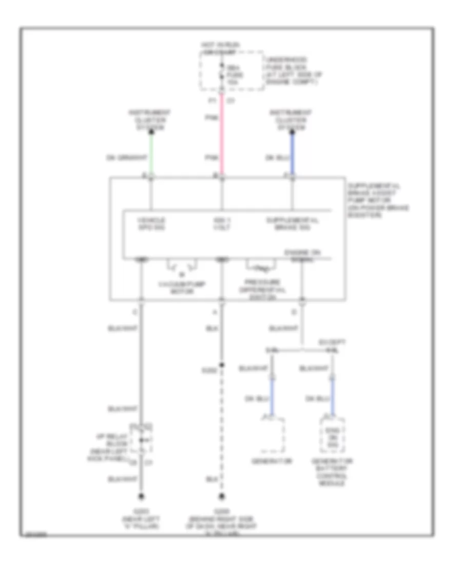
Supplemental Brake Assist Wiring Diagram for Chevrolet Cab & Chassis Silverado 3500 2007
List of elements for Supplemental Brake Assist Wiring Diagram for Chevrolet Cab & Chassis Silverado 3500 2007:
- 6.0l
- C1 f5
- C5 c1
- Eng on sig
- Engine on signal
- Except 6.0l
- G200 (behind right side of dash, near right "a" pillar)
- G203 (near left "a" pillar)
- Generator
- Generator battery control module
- Grd
- Hot in run or start
- I/p relay block (near left kick panel)
- Ign 1 volt
- Instrument cluster system
- Pnk
- Pressure differential switch
- S202
- Sba fuse 15a
- Underhood fuse block (at left side of engine compt)
- Vacuum pump motor
- Vehicle spd sig