ANTI-LOCK BRAKES
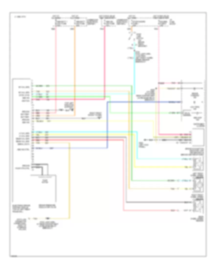
Anti-lock Brake Wiring Diagrams, with Traction Control for Chevrolet Camaro 1998

List of elements for Anti-lock Brake Wiring Diagrams, with Traction Control for Chevrolet Camaro 1998:
- (engine harn, near map sensor breakout)
- (engine harn, near pcm breakout)
- (engine harn, near vss breakout)
- (fwd lamp harn, at rear compartment lid release relay breakout)
- (fwd lamp harn, near bulkhead connector)
- (on brake pedal bracket)
- (rear of left cylinder head) g114
- (right front shock tower) g103
- +5v
- +5v ref
- A10
- A16
- Abs batt 1 maxi fuse 40a
- Abs batt mini fuse 25a
- Abs ign mini fuse 10a
- Abs ind
- Abs ind ctrl
- Abs inop ind
- Acc crtl
- Acc ctrl
- Accelerator and servo control module (under left side of dash)
- Accelerator control and adjuster (forward of right front wheel house)
- Asr (chevrolet) tcs off (pontiac)
- B c1
- B17
- Battery
- Brake malfunction indicator lamp driver module (behind center of dash)
- Brake pressure modulator valve
- Brake warning ind
- Breakout)
- C 1995 vftc
- C1 spk rtd
- C2 tach out
- Data link connector (under dash, right of steering column)
- Electronic brake and traction control module (top of left front frame rail)
- G108 (left radiator support)
- Gauges fuse 9 10a
- Ground
- Hot at all times
- Hot in run
- Hot in run, bulb test and start
- I/p fuse block
- Ign retard
- Ignition
- Instrument cluster
- Interior lights system
- Left front wheel speed sensor
- Left rear wheel speed sensor
- Lf whl spd
- Low trac ind
- Lr whl spd
- Nca
- Note: unused pins not shown
- Pnk
- Powertrain control module (behind right strut tower)
- Pump motor
- Pump mtr ctrl
- Red
- Req tps sig
- Rf whl spd
- Right front wheel speed sensor
- Right rear wheel speed sensor
- Rr whl spd
- S113
- S116
- S118
- S119
- S120
- S181
- S184
- S203
- S204
- S205
- S206
- S207
- S209
- S215
- S228 (i/p harn, 20 cm from rear compartment lid release relay breakout)
- Sec ind
- Sens gnd
- Serial data
- Solid state
- Stop lamp switch
- Stop lp fd
- Stop/hazard fuse 1 20a
- Tach signal
- Tan
- Tcs batt mini fuse 20a
- Tcs ind
- Tcs signal
- Tcs switch
- Throttle position sensor (front of throttle body)
- Torque del
- Torque req
- Tp sens
- Tps ret
- Tps sig
- Traction control switch
- Turn b/u fuse 2 20a
- Underhood electrical center 1
- Underhood electrical center 2
Anti-lock Brake Wiring Diagrams, without Traction Control for Chevrolet Camaro 1998
List of elements for Anti-lock Brake Wiring Diagrams, without Traction Control for Chevrolet Camaro 1998:
- (fwd lamp harn, at rear compartment lid release relay breakout)
- (on brake pedal bracket)
- (right front shock tower) g103
- (top left radiator support) g108
- A10
- A16
- Abs batt 1 maxi fuse 40a
- Abs batt mini fuse 25a
- Abs ign mini fuse 10a
- Abs ind
- Abs ind ctrl
- Abs inop ind
- B c1
- B17
- Battery
- Brake malfunction indicator lamp driver module (behind center of dash)
- Brake pressure modulator valve
- Brake warning ind
- C 1995 vftc
- Data link connector (under dash, right of steering column)
- Electronic brake control module (top of left front frame rail)
- G200 (left kick panel)
- Gauges fuse 9 10a
- Ground
- Hot at all times
- Hot in run, bulb test and start
- I/p fuse block
- Ignition
- Instrument cluster
- Left front wheel speed sensor
- Lf whl spd
- Low trac ind
- Nca
- Pnk
- Pump motor
- Pump mtr ctrl
- Rear wheel speed sensor
- Rear whl spd
- Red
- Rf whl spd
- Right front wheel speed sensor
- S113
- S154 (fwd lamp harn, 13 cm from left front wheel speed sensor breakout)
- S184
- S206
- S216
- S228 (i/p harn, 20 cm from rear compartment lid release relay breakout)
- Sec ind
- Serial data
- Solid state
- Stop lamp switch
- Stop lp fd
- Stop/hazard fuse 1 20a
- Tan
- Underhood electrical center 1
- Underhood electrical center 2