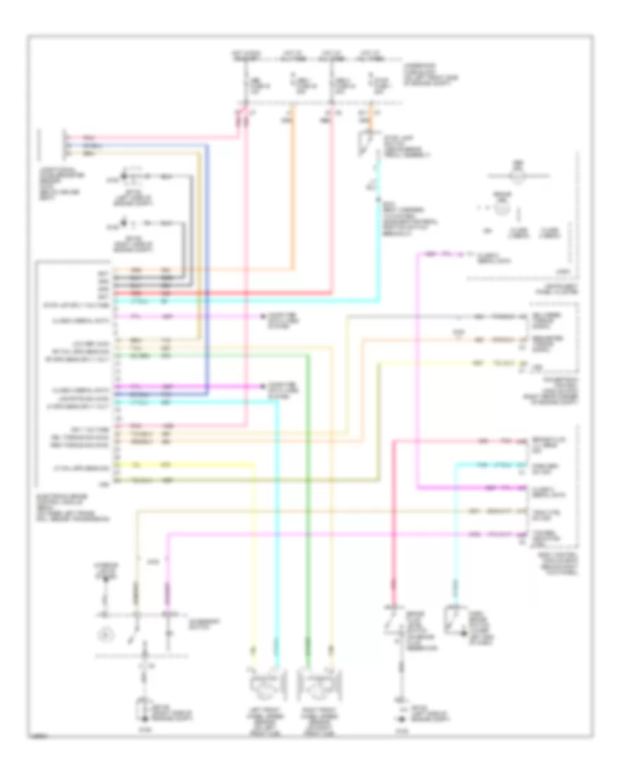
ANTI-LOCK BRAKES
Anti-lock Brakes Wiring Diagram for Chevrolet Colorado 2006
List of elements for Anti-lock Brakes Wiring Diagram for Chevrolet Colorado 2006:
- 2wd
- A17
- A26
- A31
- A39
- A45
- Abs 1 fuse 45 30a
- Abs 2 fuse 44 40a
- Abs fuse 16 10a
- Abs ind
- Accessory switch
- B c5
- Bat
- Body control module (bcm) (behind right kick panel)
- Brake fluid level switch (on brake fluid reservoir)
- Brake fluid lvl sens sig
- Brake ind
- C2 b
- C2 h
- Class 2 (ebcm)
- Class 2 serial data
- Computer data lines system
- Del torque sig (2wd)
- Delivered torque signal
- E11 c7
- Electronic brake control module (ebcm) (on inner left frame rail, beside transmission)
- G105
- G106
- Gnd
- Hot at all times
- Hot in run or start
- Ign
- Ign 1 voltage
- Instrument panel cluster
- Interior lights system
- Left front wheel speed sensor (on left front hub)
- Lf spd sens sply volt
- Lf whl spd sens sig
- Lng rate sig (4wd)
- Logic
- Longitudinal accelerometer sensor (4wd) (below driver seat)
- Low ref (4wd
- Park brake switch (lower left end of dash)
- Park brk sw sig
- Pnk
- Powertrain control module (pcm) (right rear corner of engine compt)
- Red
- Req torque sig (2wd)
- Requested torque signal
- Rf spd sens sply volt
- Rf whl spd sens sig
- Right front wheel speed sensor (on right front hub)
- S100 (body harness, 14.5 cm from accelerator pedal position switch breakout)
- Sp105 (left side of engine compt)
- Sp106 (right side of engine compt)
- Stop fuse 1 20a
- Stop lamp switch (above brake pedal assembly)
- Stop lmp sply voltage
- Tan
- Tcs req indicator ctrl
- Trac ctrl sw sig
- Underhood fuse block (on left front side of engine compt)
- Vss
 English