ANTI-LOCK BRAKES
Anti-lock Brakes Wiring Diagram (1 of 2) for Chevrolet Monte Carlo SS 2006

List of elements for Anti-lock Brakes Wiring Diagram (1 of 2) for Chevrolet Monte Carlo SS 2006:
- (5.3l: lower front of engine, under cylinder 5 exhaust port) (except 5.3l: on transmission case, below brake booster) g115
- (inside air cleaner assembly) engine control module (ecm)
- (part of brake pressure modulator valve) electronic brake control module
- (police)
- 5.3l
- Abs ind
- Abs mtr 1 fuse 60a
- Abs mtr 2 fuse 60a
- Bat pos vol
- Brake pressure modulator valve (bpmv)
- Computer data lines system
- Except 5.3l
- G115 (5.3l: lower front of engine, under cylinder 5 exhaust port) (except 5.3l: on transmission case, below brake booster)
- Gmlan (bcm)
- Gmlan (ebcm)
- Gmlan serial data
- Gmlan serial data bus +
- Gmlan serial data bus -
- Gnd
- Hot at all times
- Hsv1 (w/ tcs)
- Hsv2 (w/ tcs)
- Instrument panel cluster (ipc)
- Left front inlet
- Left front outlet
- Left rear inlet
- Left rear outlet
- Lf wheel sens lo ref
- Lf wheel sens sig
- Logic
- Lr wheel sens lo ref
- Lr wheel sens sig
- Message center
- Motor control
- Pump motor
- Rf wheel sens lo ref
- Rf wheel sens sig
- Right front inlet
- Right front outlet
- Right rear inlet
- Right rear outlet
- Rr wheel sens lo ref
- Rr wheel sens sig
- Serial data communication
- Service brake system service traction control traction control off
- Sol vlv control
- Solenoid valves
- Tan
- Traction off ind
- Underhood fuse block (mounted to right strut tower)
- Usv1 (w/ tcs)
- Usv2 (w/ tcs)
- Vehicle spd sig
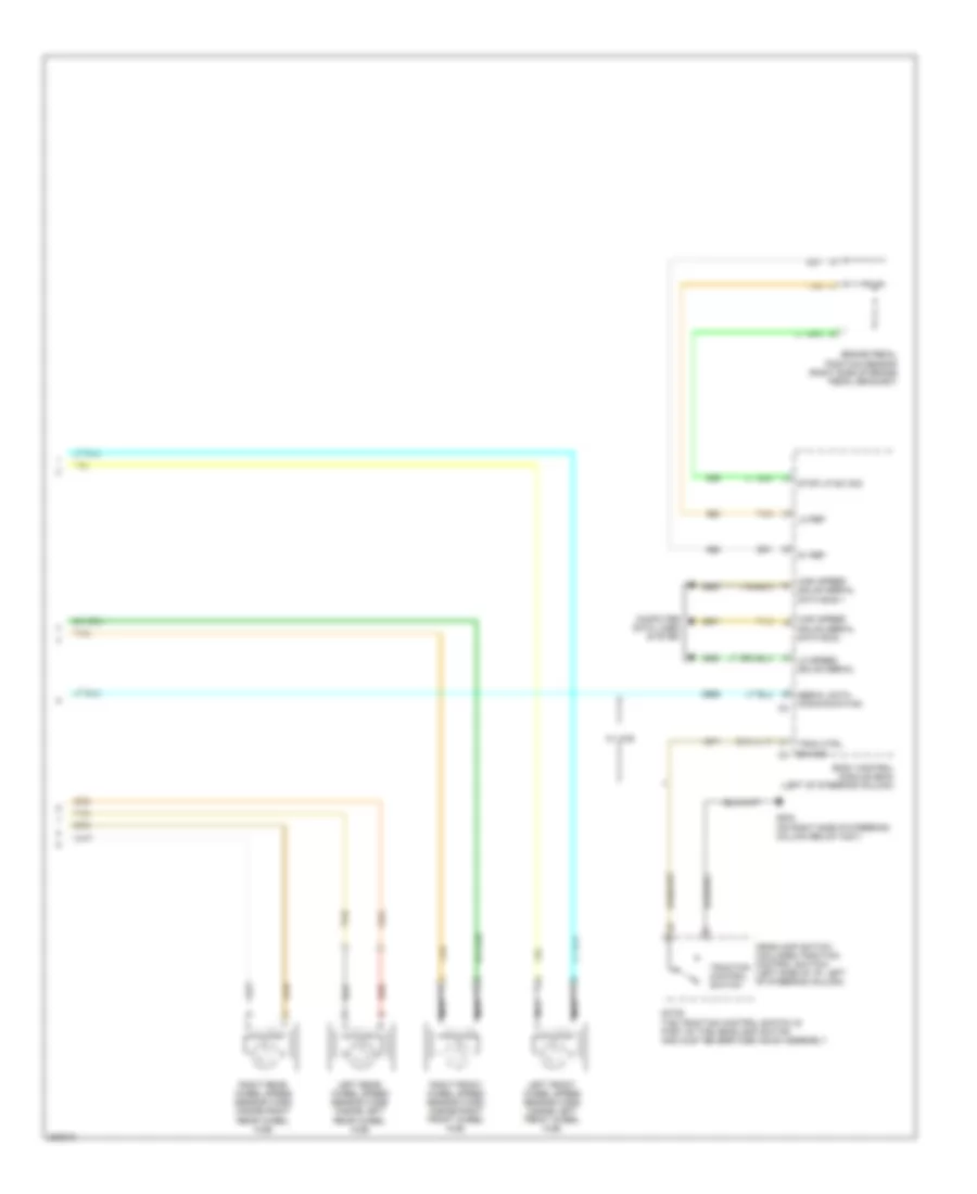
Anti-lock Brakes Wiring Diagram (2 of 2) for Chevrolet Monte Carlo SS 2006
List of elements for Anti-lock Brakes Wiring Diagram (2 of 2) for Chevrolet Monte Carlo SS 2006:
- 5v ref
- Body control module (bcm) (left of steering column)
- Brake pedal position sensor (right side of brake pedal bracket)
- Computer data lines system
- G202 (on right side of steering column below c201)
- Headlamp switch (includes traction control switch) (left side of i/p, left of steering column)
- High speed gmlan serial data bus +
- High speed gmlan serial data bus -
- Left front wheel speed sensor (wss) (inside left front wheel hub)
- Left rear wheel speed sensor (wss) (inside left rear wheel hub)
- Lo ref
- Lo speed gmlan serial
- Nca
- Note: the traction control switch is part of the headlamp switch and must be serviced as an assembly.
- Red
- Right front wheel speed sensor (wss) (inside right front wheel hub)
- Right rear wheel speed sensor (wss) (inside right rear wheel hub)
- Serial data communication
- Stop lp sw sig
- Tan
- Trac ctrl sw sig
- Traction control switch
- W/ vcs