ANTI-LOCK BRAKES
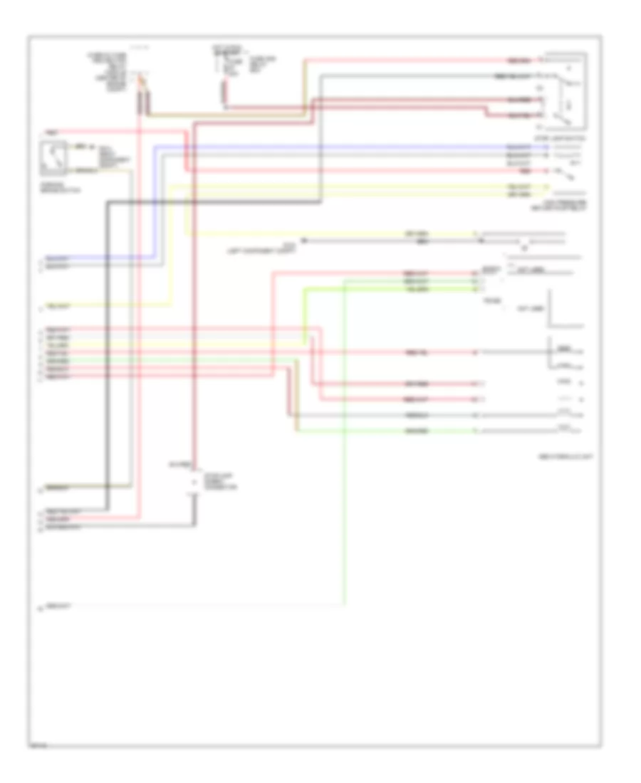
Anti-lock Brake Wiring Diagrams (1 of 2) for Mercedes-Benz C220 1996

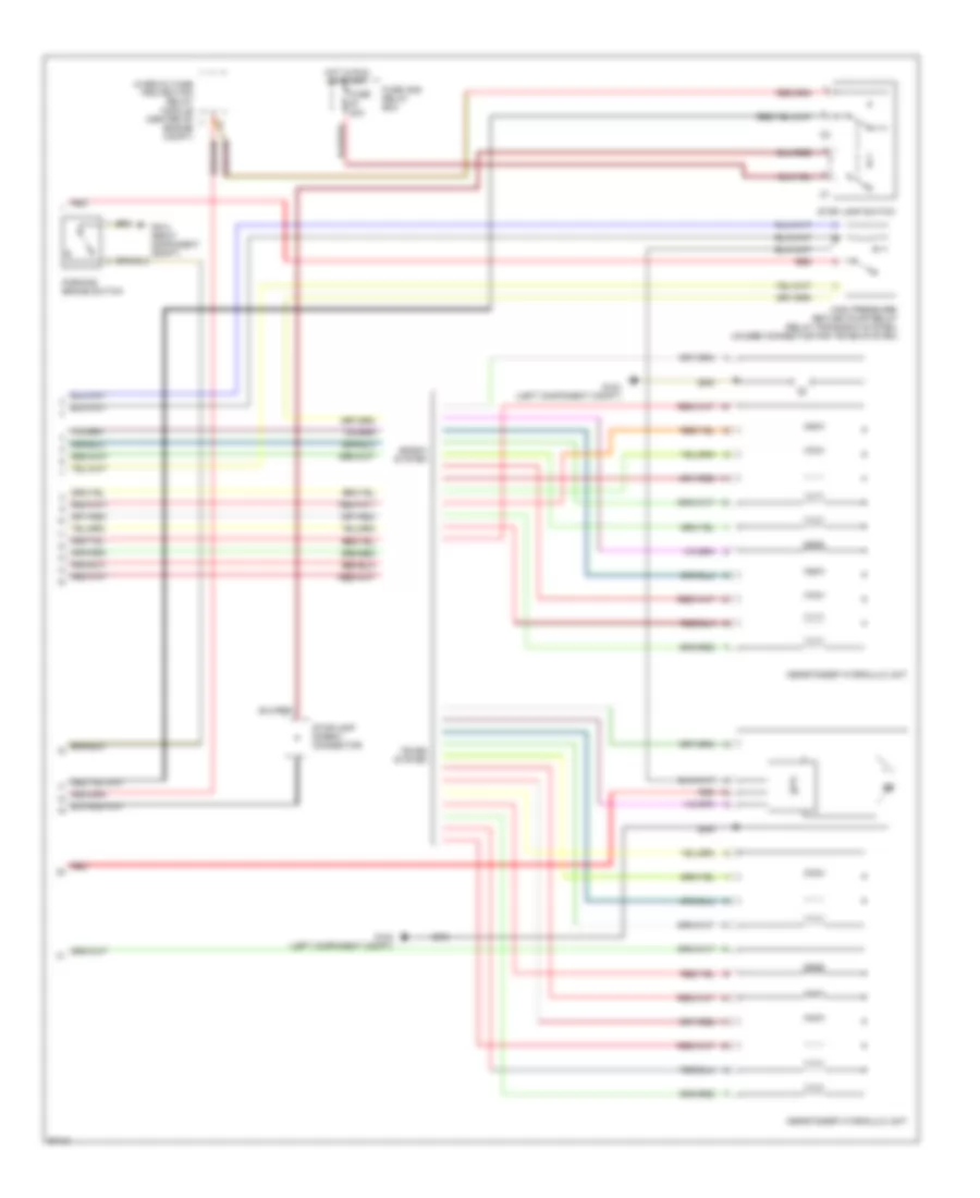
List of elements for Anti-lock Brake Wiring Diagrams (1 of 2) for Mercedes-Benz C220 1996:
- Abs control module (right rear of engine compt)
- Abs mil
- Brake pad wear ind
- Cc/isc control module
- Data link connector (right rear of engine compt)
- Engine controls system, instrument cluster (vehicle speed signal)
- Fuse 3 7.5a
- Fuse and relay box
- G105 (right component compt)
- Hot at all times
- Hot in run or start
- Instrument cluster
- Left front axle vss speed sensor
- Left front brake pad wear sensor
- Left rear axle vss speed sensor
- Low brake fluid/ park brake ind
- Nca
- Red
- Right front axle vss speed sensor
- Right front brake pad wear sensor
- Terminal block (x12/3)
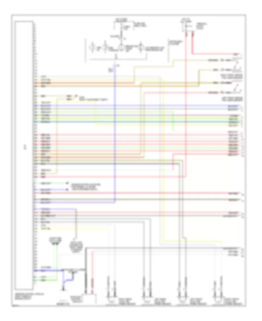
Anti-lock Brake Wiring Diagrams (2 of 2) for Mercedes-Benz C220 1996
List of elements for Anti-lock Brake Wiring Diagrams (2 of 2) for Mercedes-Benz C220 1996:
- Abs hydraulic unit
- Bosch
- Fuse 20a
- Fuse and relay box
- G104 (left component compt)
- G104 (right component compt)
- High pressure/ return pump relay
- Hot in run or start
- Not used
- Overvoltage protection relay module (center of engine compt)
- Parking brake switch
- Red
- Stop lamp switch
- Stoplamp screw connector
- Teves
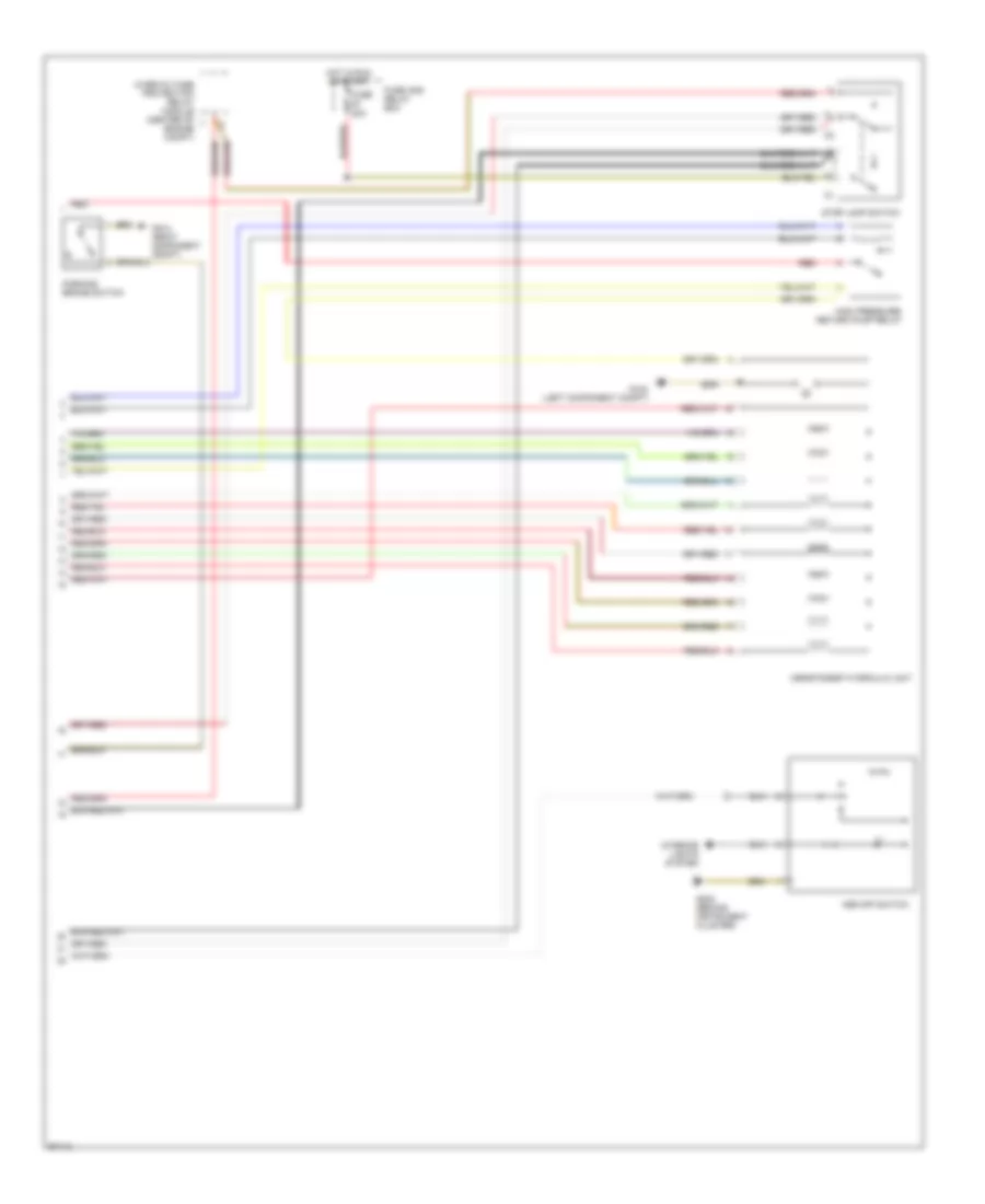
Anti-lock Brake Wiring Diagrams, with Acceleration Slip Regulation (1 of 2) for Mercedes-Benz C220 1996
List of elements for Anti-lock Brake Wiring Diagrams, with Acceleration Slip Regulation (1 of 2) for Mercedes-Benz C220 1996:
- Asr mil
- Asr warning
- Asr/sps control module (right rear of engine compt)
- Brake pad wear ind
- Computer data lines system
- Data link connector (right rear of engine compt)
- Ea/cc/isc control module
- Engine controls system, instrument cluster (vehicle speed signal)
- Fuse 3 7.5a
- Fuse and relay box
- G105 (right component compt)
- Generator
- Hot at all times
- Hot in run or start
- Instrument cluster
- Instrument cluster system
- Left front axle vss speed sensor
- Left front brake pad wear sensor
- Left rear axle vss speed sensor
- Low brake fluid/ park brake ind
- Nca
- Red
- Right front axle vss speed sensor
- Right front brake pad wear sensor
- Right rear axle vss speed sensor
- Terminal block (x12/3)
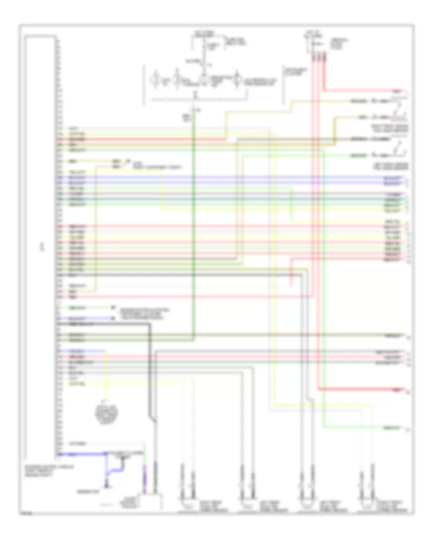
Anti-lock Brake Wiring Diagrams, with Acceleration Slip Regulation (2 of 2) for Mercedes-Benz C220 1996
List of elements for Anti-lock Brake Wiring Diagrams, with Acceleration Slip Regulation (2 of 2) for Mercedes-Benz C220 1996:
- Asr off switch
- Asr/ets/esp hydraulic unit
- Fuse 20a
- Fuse and relay box
- G104 (left component compt)
- G104 (right component compt)
- G202 (behind instrument cluster)
- High pressure/ return pump relay
- Hot in run or start
- Interior lights system
- Overvoltage protection relay module (center of engine compt)
- Parking brake switch
- Red
- Stop lamp switch
Anti-lock Brake Wiring Diagrams, with Traction Control (1 of 2) for Mercedes-Benz C220 1996
List of elements for Anti-lock Brake Wiring Diagrams, with Traction Control (1 of 2) for Mercedes-Benz C220 1996:
- Brake pad wear ind
- Cc/isc control module
- Data link connector (right rear of engine compt)
- Engine controls system, instrument cluster (vehicle speed signal)
- Ets mil
- Ets warning
- Ets/sps control module (right rear of engine compt)
- Fuse 3 7.5a
- Fuse and relay box
- G105 (right component compt)
- Generator
- Hot at all times
- Hot in run or start
- Instrument cluster
- Instrument cluster system
- Left front axle vss speed sensor
- Left front brake pad wear sensor
- Left rear axle vss speed sensor
- Low brake fluid/ park brake ind
- Nca
- Red
- Right front axle vss speed sensor
- Right front brake pad wear sensor
- Right rear axle vss speed sensor
- Terminal block (x12/3)
Anti-lock Brake Wiring Diagrams, with Traction Control (2 of 2) for Mercedes-Benz C220 1996
List of elements for Anti-lock Brake Wiring Diagrams, with Traction Control (2 of 2) for Mercedes-Benz C220 1996:
- Asr/ets/esp hydraulic unit
- Bosch system
- Fuse 20a
- Fuse and relay box
- G104 (left component compt)
- G104 (right component compt)
- High pressure/ return pump relay (relay for bosch system, unused connector for teves system)
- Hot in run or start
- Overvoltage protection relay module (center of engine compt)
- Parking brake switch
- Red
- Stop lamp switch
- Stoplamp screw connector
- Teves system