ANTI-LOCK BRAKES
Anti-lock Brake Wiring Diagrams for Subaru Legacy Brighton 1998
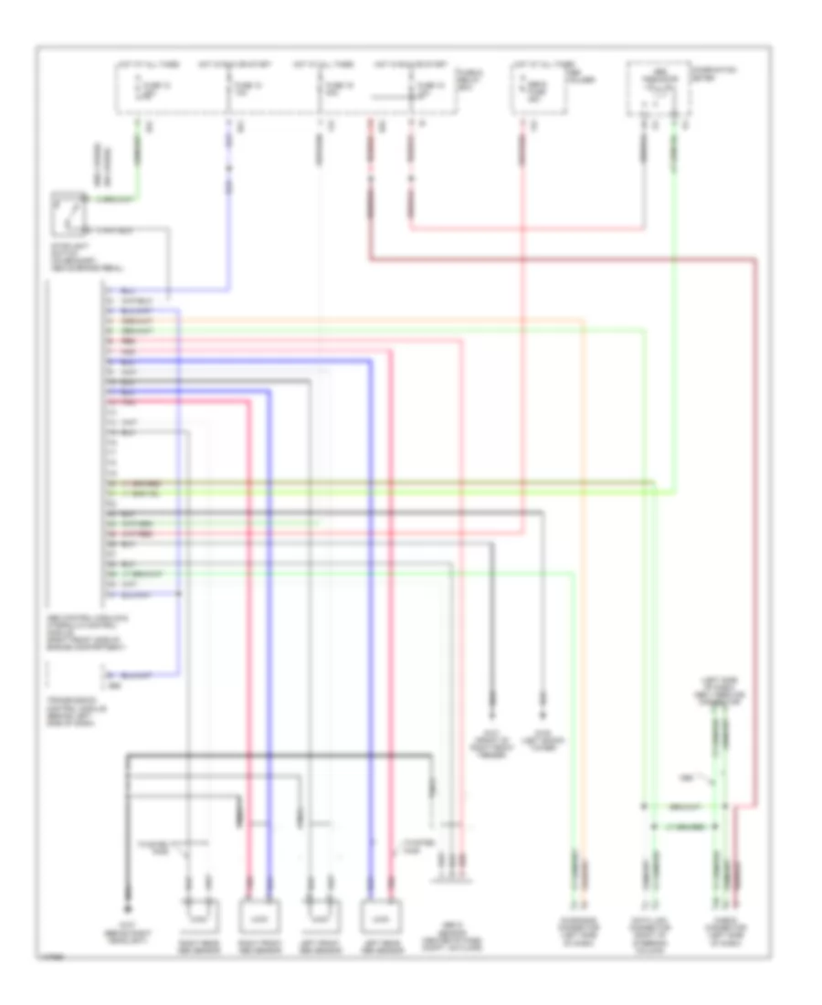
List of elements for Anti-lock Brake Wiring Diagrams for Subaru Legacy Brighton 1998:
- (left side of dash) obd ii service connector
- (w/o cruise)
- Abs control module & hydraulic control module (right front side of engine compartment)
- Abs g sensor (center of pass compt, on floor)
- Abs indicator
- B51
- B52
- B56
- Check connector (left side of dash)
- Combination meter
- Data link connector (right of steering column)
- Diagnosis connector (left side of dash)
- F34
- F42
- Fuse & relay box
- Fuse 12 20a
- Fuse 15 10a
- Fuse 18 10a
- Fuse 19 20a
- G101 (front of right front fender)
- G102 (left shock tower)
- G107 (behind right headlight)
- Hot at all times
- Hot in run or start
- I14
- Left front abs sensor
- Left rear abs sensor
- Nca
- Pnk
- Red
- Right front abs sensor
- Right rear abs sensor
- Sbf holder
- Sbf-6 fuse 45a
- Stoplight switch (on bracket, above brake pedal)
- Transmission control module (behind left side of dash)
- Twisted pair
 English