ANTI-LOCK BRAKES
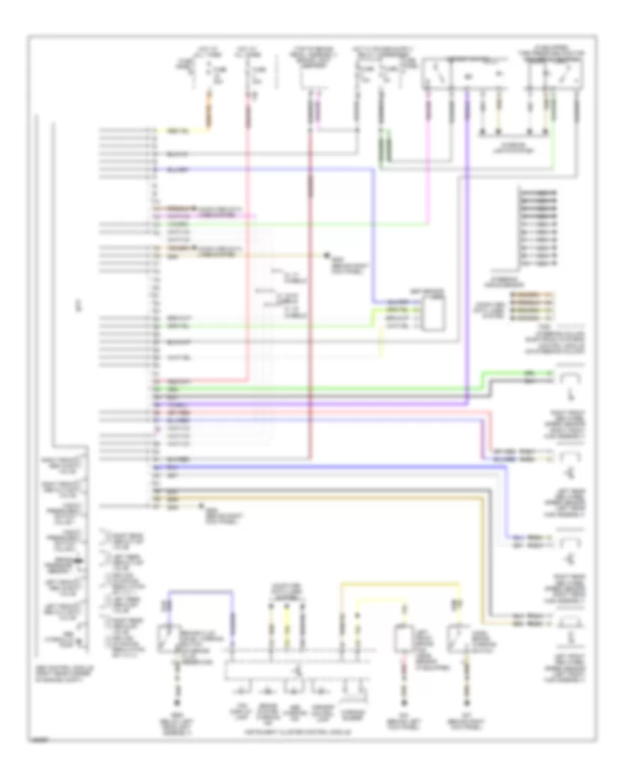
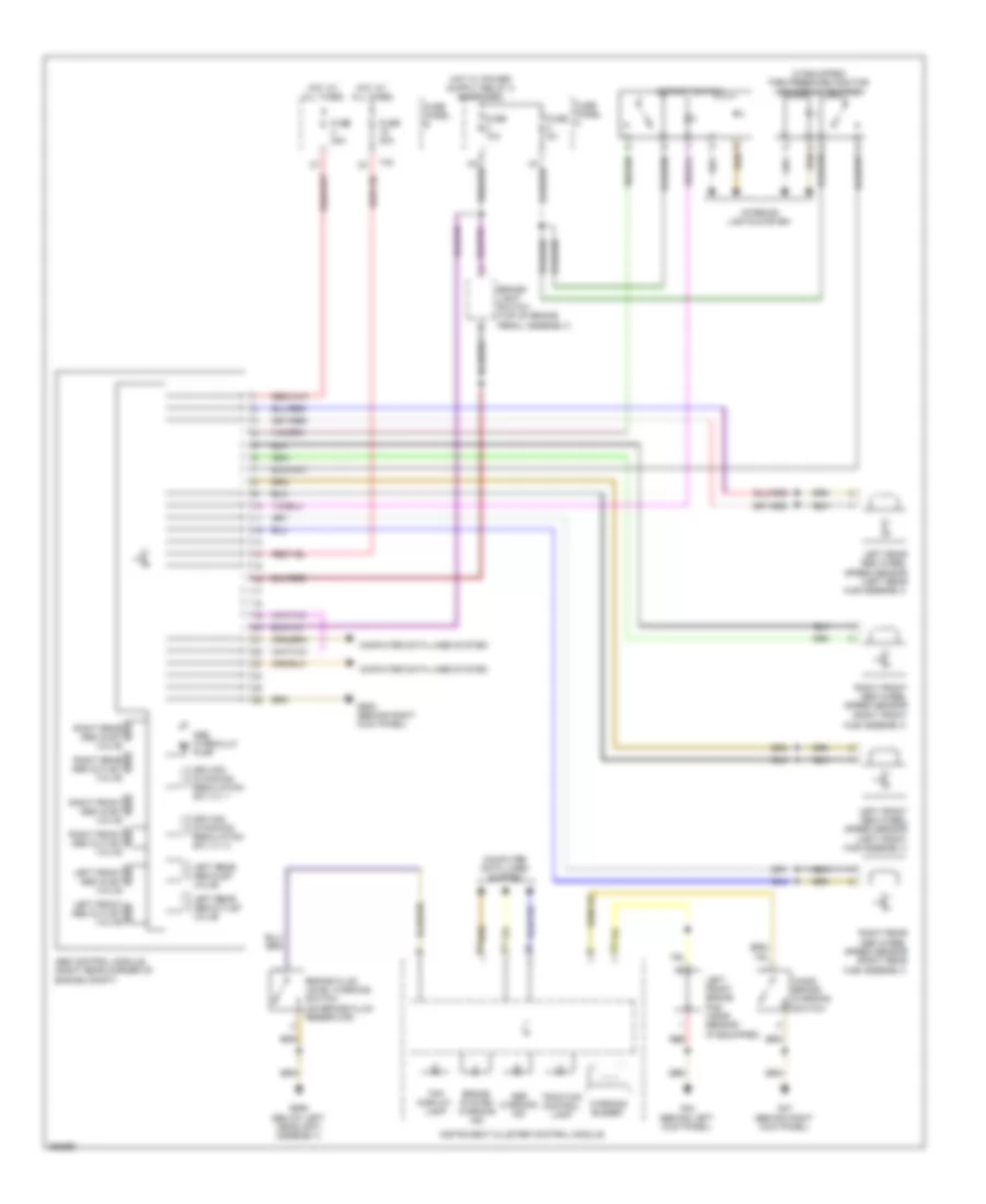
Anti-lock Brakes Wiring Diagram, with ESP, EDL & ASR for Volkswagen Rabbit S 2008

List of elements for Anti-lock Brakes Wiring Diagram, with ESP, EDL & ASR for Volkswagen Rabbit S 2008:
- (if equipped) tire pressure monitor- ing display button
- (top of brake pedal assembly) brake light switch
- 14a
- Abs control module (right rear corner of engine compt)
- Abs hydraulic pump
- Abs warning ind
- Asr/esp control lamp
- Asr/esp switch
- Brake booster vacuum sensor (if equipped)
- Brake fluid level warning switch (on brake fluid reservoir)
- Brake pressure sensor 1
- Brake system warning ind
- Computer data lines system
- Computer data lines system g638 (behind right kick panel)
- Driving dynamics regulation sw vlv 1
- Esp sensor unit
- Fuse 10a
- Fuse 30a
- Fuse 5a
- Fuse panel b
- Fuse panel c
- G44 (behind left kick panel)
- G47 (behind right kick panel)
- G638 (behind right kick panel)
- G655 (below left headlight assembly)
- Hand- brake warning switch
- High pressure switch valve 1
- Hot at all times
- Instrument cluster control module
- Interior lights system
- Left front abs inlet valve
- Left front abs outlet valve
- Left front abs wheel speed sensor (left front hub assembly)
- Left front brake pad wear sensor (if equipped)
- Left rear abs inlet valve
- Left rear abs outlet valve
- Left rear abs wheel speed sensor (left rear hub assembly)
- Nca
- Red
- Right front abs inlet valve
- Right front abs outlet valve
- Right front abs wheel speed sensor (right front hub assembly)
- Right rear abs inlet valve driving dynamics regulation sw vlv 2
- Right rear abs outlet valve
- Right rear abs wheel speed sensor (right rear hub assembly)
- Steering angle sensor
- Steering column electronic systems control module (on steering column)
- T20d
- T40
- Tpm display lamp
- W/ 15" wheels
- W/ 15/16" wheels
- W/ 17" wheels
- Warning buzzer
Anti-lock Brakes Wiring Diagram, with ESP, EDS & ASR for Volkswagen Rabbit S 2008
List of elements for Anti-lock Brakes Wiring Diagram, with ESP, EDS & ASR for Volkswagen Rabbit S 2008:
- (if equipped) tire pressure monitor- ing display button
- (top of brake pedal assembly) brake light switch
- Abs control module (right rear corner of engine compt)
- Abs hydraulic pump
- Abs warning ind
- Asr/esp control lamp
- Asr/esp switch
- Brake fluid level warning switch (on brake fluid reservoir)
- Brake pressure sensor 1
- Brake system warning ind
- Computer data lines system
- Driving dynamics regulation sw vlv 1
- Esp sensor unit
- Fuse 10a
- Fuse 30a
- Fuse 5a
- Fuse panel b
- Fuse panel c
- G44 (behind left kick panel)
- G47 (behind right kick panel)
- G638 (behind right kick panel)
- G655 (below left headlight assembly)
- Hand- brake warning switch
- High pressure switch valve 1
- High pressure switch valve 2
- Hot at all times
- Instrument cluster control module
- Interior lights system
- Left front abs inlet valve
- Left front abs outlet valve
- Left front abs wheel speed sensor (left front hub assembly)
- Left front brake pad wear sensor (if equipped)
- Left rear abs inlet valve
- Left rear abs outlet valve
- Left rear abs wheel speed sensor (left erar hub assembly)
- Nca
- Red
- Right front abs inlet valve
- Right front abs outlet valve
- Right front abs wheel speed sensor (right front hub assembly)
- Right rear abs inlet valve driving dynamics regulation sw vlv 2
- Right rear abs outlet valve
- Right rear abs wheel speed sensor (right rear hub assembly)
- Steering angle sensor
- Steering column electronic systems control module (on steering column)
- T20d
- T40
- Tpm display lamp
- W/ 15" wheels
- W/ 15/16" wheels
- W/ 17" wheels
- Warning buzzer
Anti-lock Brakes Wiring Diagram, without ESP for Volkswagen Rabbit S 2008
List of elements for Anti-lock Brakes Wiring Diagram, without ESP for Volkswagen Rabbit S 2008:
- (if equipped) tire pressure monitor- ing display button
- (right front hub assembly)
- Abs control module (right rear corner of engine compt)
- Abs hydraulic pump
- Abs warning ind
- Asr/esp switch
- Brake fluid level warning switch (on brake fluid reservoir)
- Brake system warning ind
- Brake- light switch (top of brake pedal assembly)
- Computer data lines system
- Driving dynamics regulation sw vlv 1
- Driving dynamics regulation sw vlv 2
- Fuse 10a
- Fuse 30a
- Fuse 5a
- Fuse panel b
- Fuse panel c
- G44 (behind left kick panel)
- G47 (behind right kick panel)
- G638 (behind right kick panel)
- G655 (below left headlight assembly)
- Hand- brake warning switch
- Hot at all times
- Instrument cluster control module
- Interior lights system
- Left front abs inlet valve
- Left front abs outlet valve
- Left front abs wheel speed sensor (left front hub assembly)
- Left front brake pad wear sensor (if equipped)
- Left rear abs inlet valve
- Left rear abs outlet valve
- Left rear abs wheel speed sensor (left rear hub assembly)
- Red
- Right front abs inlet valve
- Right front abs outlet valve
- Right front abs wheel speed sensor
- Right rear abs inlet valve
- Right rear abs outlet valve
- Right rear abs wheel speed sensor (right rear hub assembly)
- T40
- Tpm display lamp
- Traction control lamp
- Warning buzzer