COMPUTER DATA LINES
Data Link Connector Wiring Diagram for Mercedes-Benz C320 2005

List of elements for Data Link Connector Wiring Diagram for Mercedes-Benz C320 2005:
- (1.8l)
- (except 1.8l)
- C10
- C20
- C24
- Can h
- Can l
- Central gateway control unit (under steering column)
- Computer data lines system (high/low bus circuit)
- Datalink connector (under left side of dash)
- Di control module
- Diag
- Electronic selector lever module
- Engine control module (left rear of engine compt)
- Esp & bas control module (left side of engine compt)
- Etc control module (under right side of dash)
- Front pre-fuse box (right rear of engine compt)
- Front sam control module w/ fuse & relay module (left rear of engine compt)
- Fuse 200a
- Fuse 5a
- Hot at all times
- Left headlamp unit
- Pnk/red
- Red
- Right headlamp unit
- W16/3 (left side of engine compt)
- W16/5 (left rear of engine compt)
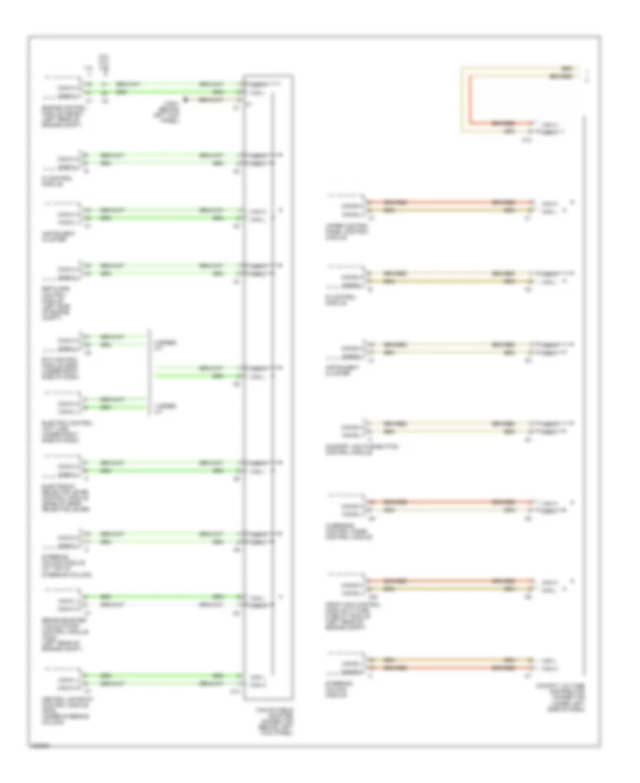
High/Low Bus Wiring Diagram (1 of 2) for Mercedes-Benz C320 2005
List of elements for High/Low Bus Wiring Diagram (1 of 2) for Mercedes-Benz C320 2005:
- 1.8l
- 2.5l, 3.0l, 3.5l
- 5 speed a/t
- 7 speed a/t
- Brake booster vacuum pump control module (c230) (left rear of engine compt)
- C10
- C20
- Can databus adapter connector (behind left kick panel)
- Can h
- Can l
- Can-b h
- Can-b l
- Can-c h
- Can-c l
- Central gateway control module (2005) (under steering column)
- Cockpit voltage distributor connector (under left side of dash)
- Comfort aac pushbutton control module
- Di control module
- Electric control unit (vgs) (under right side of dash)
- Electronic selector lever control module (base of gear selector lever)
- Engine control module (me-sfi) (left rear of engine compt)
- Esp & bas control module (left side of engine compt)
- Etc control module (egs) (under right side of dash)
- Front sam control module w/ fuse & relay module (left rear of engine compt)
- Instrument cluster
- Overhead control panel control module
- Steering column module
- Steering column module (at top of steering column)
- Upper control panel control module
- W28/1 (behind left kick panel)
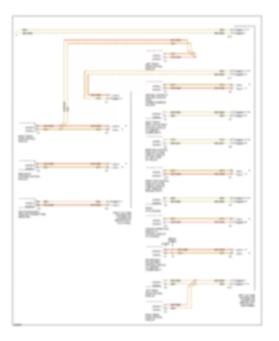
High/Low Bus Wiring Diagram (2 of 2) for Mercedes-Benz C320 2005
List of elements for High/Low Bus Wiring Diagram (2 of 2) for Mercedes-Benz C320 2005:
- C10
- C11
- Can h
- Can l
- Can-b h
- Can-b l
- Central gateway control module (2005) (under steering column)
- Comand operating, display & control module (w/ comand)
- Coupe
- D2b telephone & tele aid transmitter/ receiver
- Driver seat adjustment control module (w/ memory) (under seat)
- Front sam control module w/ fuse & relay module (left rear of engine compt)
- J10
- Left front door control module
- Left rear door control module
- Left voltage distributor connector (behind left kick panel) kick panel)
- Radio (w/o comand)
- Rear sam control module w/ fuse & relay module (at left side of trunk)
- Restraint systems control module
- Right front door control module
- Right front seat adjustment control module (w/ memory) (under seat)
- Right rear door control module
- Right voltage distributor connector (behind right kick panel)
- Sedan, wagon