COMPUTER DATA LINES
Data Link Connector Wiring Diagram for Mercedes-Benz CLK500 2006

List of elements for Data Link Connector Wiring Diagram for Mercedes-Benz CLK500 2006:
- (behind right kick panel) etc (egs) control module
- 3.5l
- 5.0l
- C10
- C24
- Data link connector (under left side of dash)
- Eis (ezs) control unit
- Electronic control unit (vgs) (under automatic gear box)
- Front sam control module fuse & relay module (left rear of engine compt)
- Fuse 5a
- Hot at all times
- Left front headlamp unit
- Me-sfi (me) control module (in front sam control module)
- Navigation system
- Pnk/red
- Right front headlamp unit
- W/ 7-speed automatic transmission
- W/ electronic transmission
- W16/3 (at left front of engine compt)
- W16/5 (left rear of engine compt)
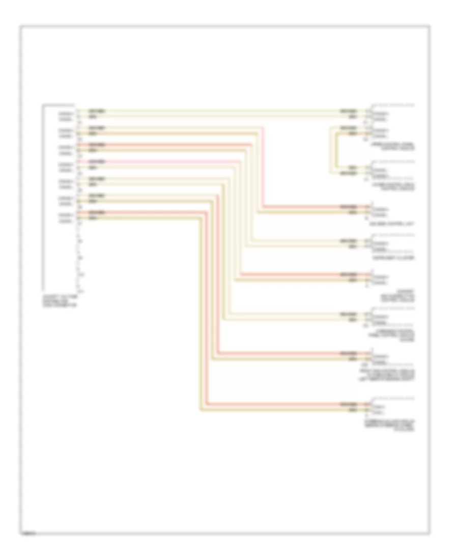
High/Low Bus Wiring Diagram (1 of 3) for Mercedes-Benz CLK500 2006
List of elements for High/Low Bus Wiring Diagram (1 of 3) for Mercedes-Benz CLK500 2006:
- C10
- C11
- C20
- Can h
- Can l
- Can-b h
- Can-b l
- Cockpit voltage distributor (can) connector
- Comfort aac pushbutton control module
- Eis (ezs) control unit
- Front sam control module w/ fuse & relay module (left rear of engine compt)
- Instrument cluster
- Lower control field control module
- Overhead control panel control module (coupe)
- Steering column module (behind steering wheel, in column)
- Upper control panel control module
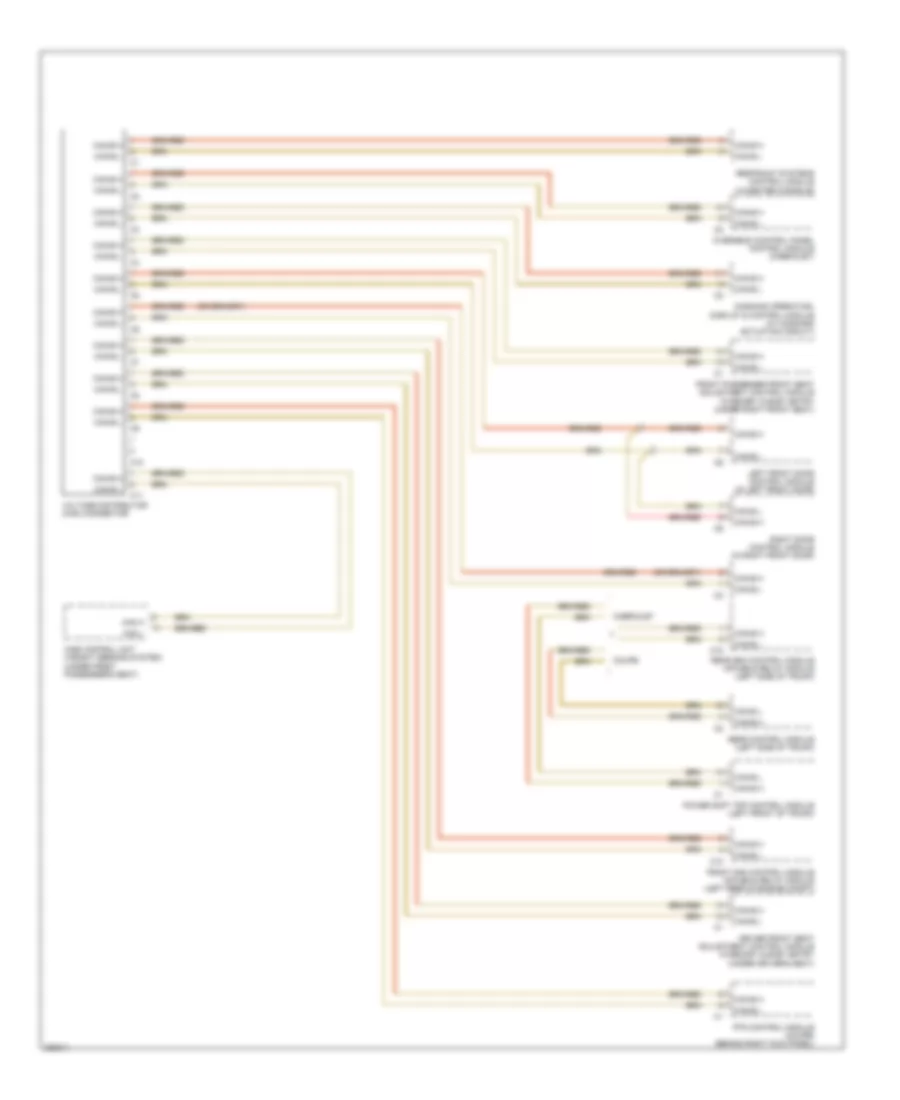
High/Low Bus Wiring Diagram (2 of 3) for Mercedes-Benz CLK500 2006
List of elements for High/Low Bus Wiring Diagram (2 of 3) for Mercedes-Benz CLK500 2006:
- C10
- C11
- C18
- Cabriolet
- Can h
- Can l
- Can-b h
- Can-b l
- Command operating, display & control module (w/ command actuation circuit)
- Coupe
- Driver front seat adjustment control module w/memory & easy entry (under driver's seat)
- Front passenger front seat adjustment control module w/memory & easy entry (under right front seat)
- Front sam control module w/fuse & relay module (left rear of engine compt)
- Left front door control module (in left front door)
- Overhead control panel control module (cabriolet)
- Power soft top control module (left front of trunk)
- Pts control module (coupe) (behind right kick panel)
- Rear control module (left side of trunk)
- Rear sam control module w/fuse & relay module (left side of trunk)
- Restraint systems control module (in center console)
- Right door control module (in right front door)
- Voltage distributor (can) connector
- Wss control unit (weight sensing system) (under front passenger's seat)
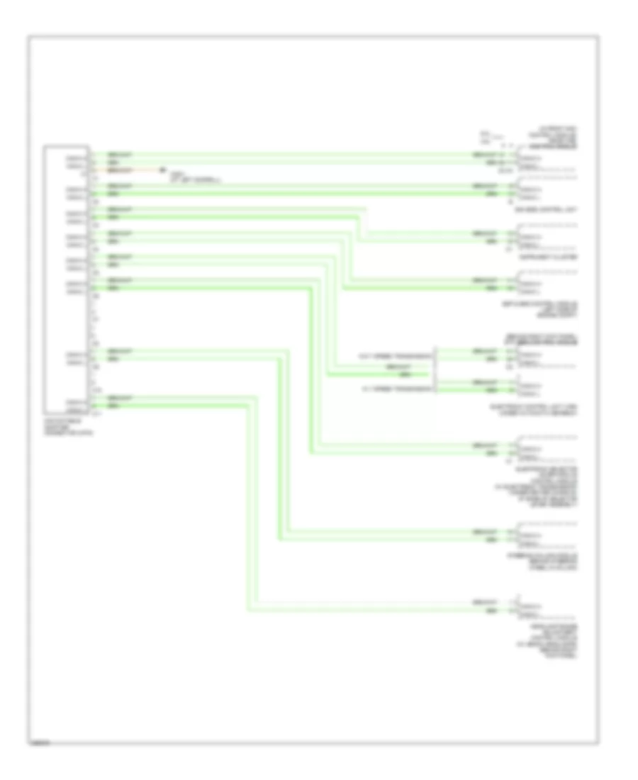
High/Low Bus Wiring Diagram (3 of 3) for Mercedes-Benz CLK500 2006
List of elements for High/Low Bus Wiring Diagram (3 of 3) for Mercedes-Benz CLK500 2006:
- (behind right kick panel) etc (ezs) control module
- (in front sam control module) me-sfi (me) control module
- 3.5l
- 5.0l
- C10
- C11
- Can databus adapter connector (2-pin)
- Can-c h
- Can-c l
- Eis (ezs) control unit
- Electronic control unit (vgs) (under automatic gearbox)
- Electronic selector lever module control module (w/ electronic transmission) (under center console, at base of selector lever assembly)
- Esp & bas control module (left side of engine compt)
- Headlamp range adjustment control module (w/ xenon headlamps) (behind right kick panel)
- Instrument cluster
- Steering column module (behind steering wheel,in column)
- W/ 7 speed transmission
- W/o 7 speed transmission
- W28/1 (at left doorsill)