COMPUTER DATA LINES
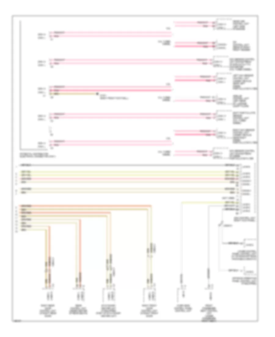
Data Link Connector Wiring Diagram for Mercedes-Benz GL450 2014

List of elements for Data Link Connector Wiring Diagram for Mercedes-Benz GL450 2014:
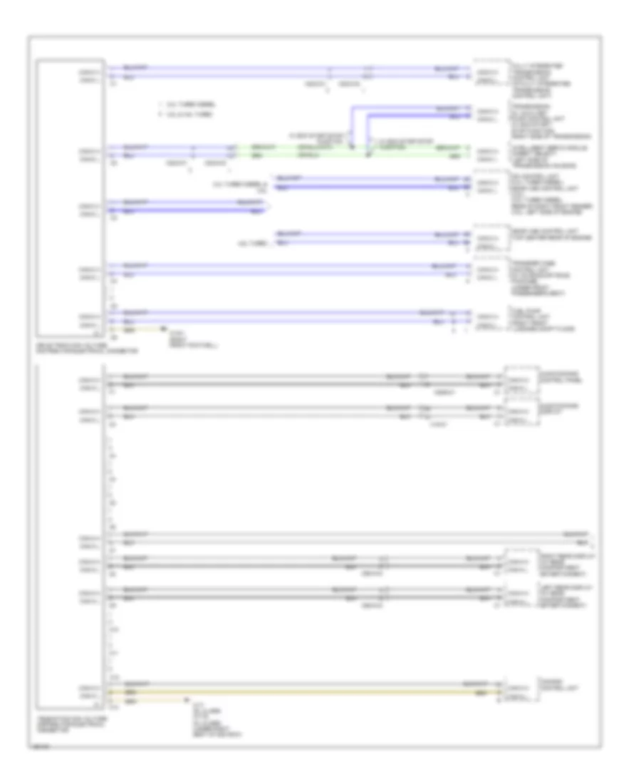
High/Low Bus Wiring Diagram (1 of 5) for Mercedes-Benz GL450 2014
List of elements for High/Low Bus Wiring Diagram (1 of 5) for Mercedes-Benz GL450 2014:
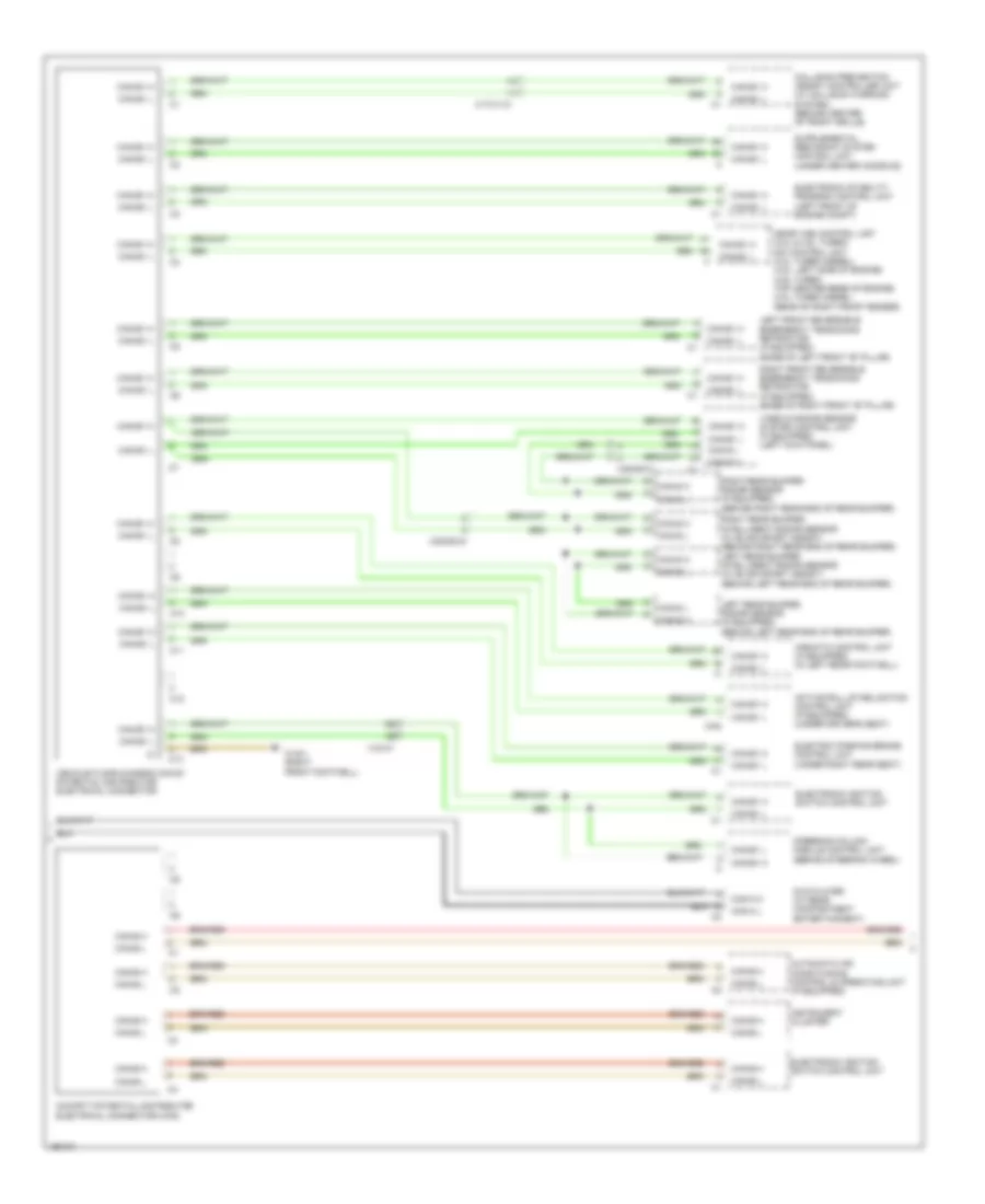
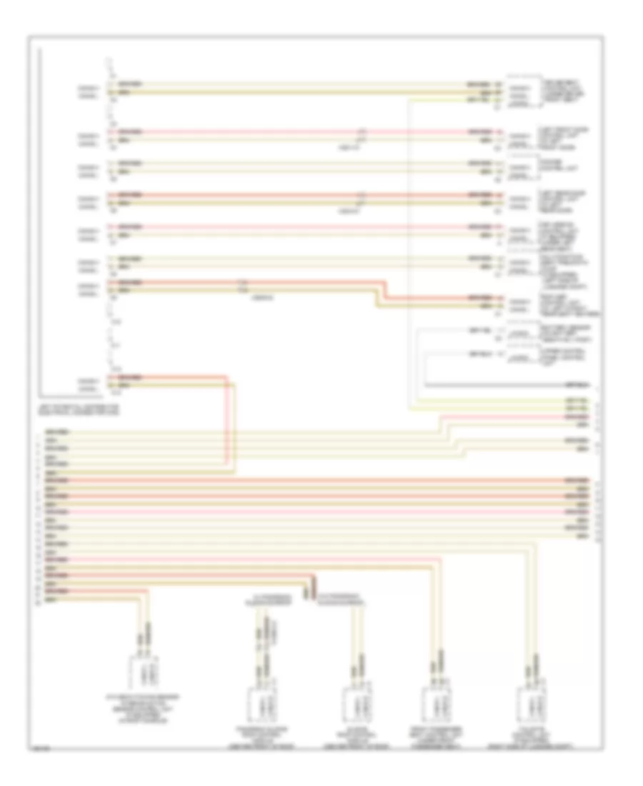
High/Low Bus Wiring Diagram (2 of 5) for Mercedes-Benz GL450 2014
List of elements for High/Low Bus Wiring Diagram (2 of 5) for Mercedes-Benz GL450 2014:
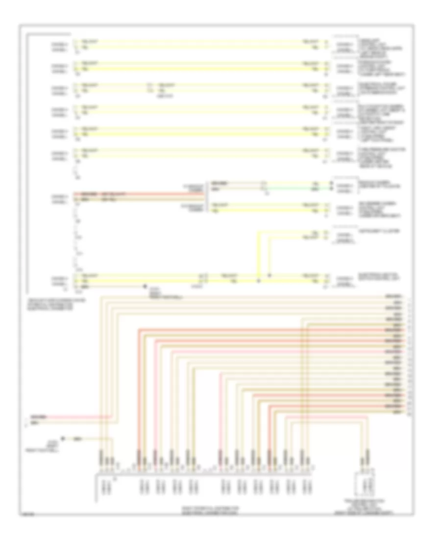
High/Low Bus Wiring Diagram (3 of 5) for Mercedes-Benz GL450 2014
List of elements for High/Low Bus Wiring Diagram (3 of 5) for Mercedes-Benz GL450 2014:
High/Low Bus Wiring Diagram (4 of 5) for Mercedes-Benz GL450 2014
List of elements for High/Low Bus Wiring Diagram (4 of 5) for Mercedes-Benz GL450 2014:
High/Low Bus Wiring Diagram (5 of 5) for Mercedes-Benz GL450 2014
List of elements for High/Low Bus Wiring Diagram (5 of 5) for Mercedes-Benz GL450 2014: