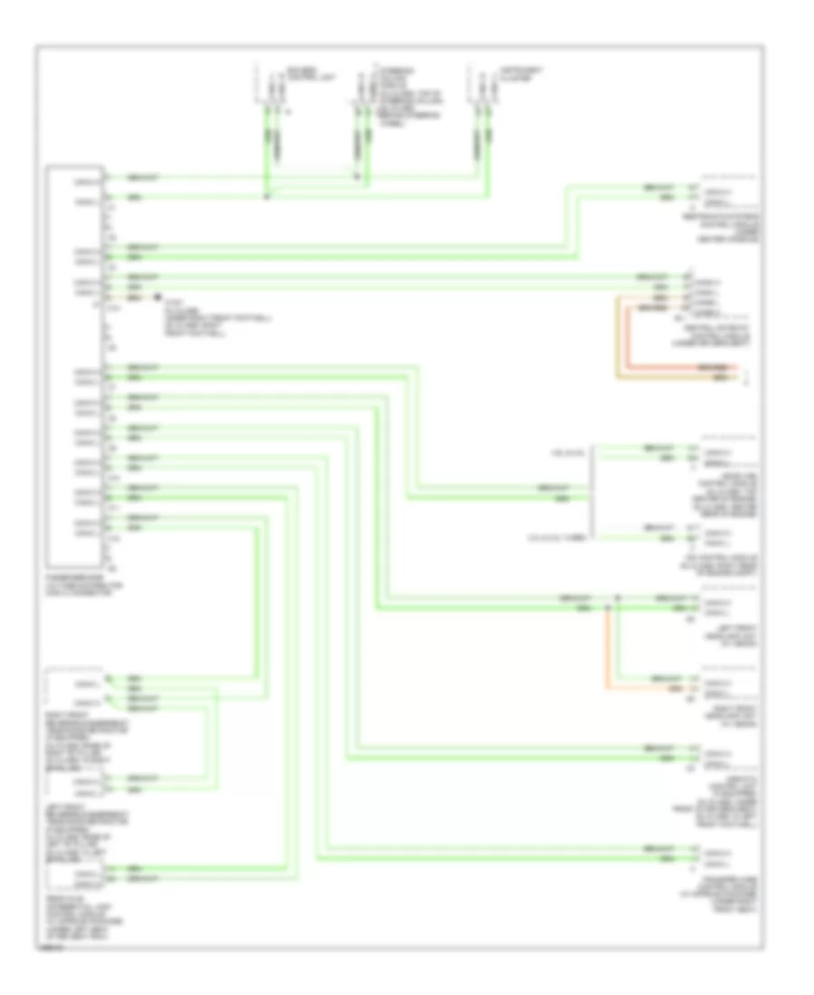
COMPUTER DATA LINES
Data Link Connector Wiring Diagram for Mercedes-Benz ML350 2008

List of elements for Data Link Connector Wiring Diagram for Mercedes-Benz ML350 2008:
- (ml-class: under left front footwell) (gl-class: left front footwell) w15/2
- (under left seat of 2nd seat row) (w/ tele aid emergency system) emergency call system control unit
- 3.0l turbo
- C13
- Can-b h
- Can-b l
- Can-c h
- Can-c l
- Can-d h
- Can-d l
- Central gateway control module (under driver's seat)
- Circuit 31 left footwell voltage distributor connector 1
- Data link connector (dlc) (below left side of dash)
- Except 3.0l turbo
- Fuse 7.5a
- Hot at all times
- Left fuel pump control unit (under right seat of 2nd seat row)
- Load compartment fuse & relay box (ml-class: right rear of cargo area) (gl-class: right side of cargo area)
- Passenger-side voltage distributor (can c) connector
- Red
- Right fuel pump control unit (under right seat of 2nd seat row)
- Sl1
- Sl2
- Voltage distributor (can) connector
- W15/1 (ml-class: under right front footwell) (gl-class: right front footwell)
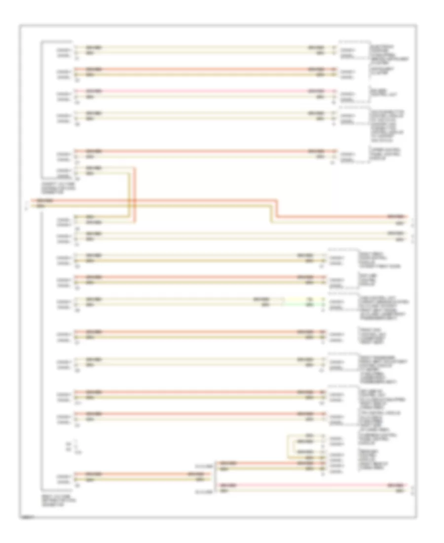
High/Low Bus Wiring Diagram (1 of 3) for Mercedes-Benz ML350 2008
List of elements for High/Low Bus Wiring Diagram (1 of 3) for Mercedes-Benz ML350 2008:
- (gl-class: center rear of engine)
- 3.0l & 3.0l turbo
- 4.6l & 3.5l
- Airmatic control unit (if equipped) (ml-class: under front of driver's seat) (gl-class: in left front footwell)
- C10
- C11
- C12
- C13
- Can-b h
- Can-b l
- Can-c h
- Can-c l
- Cdi control module (gl-class: right rear of engine compt)
- Central gateway control module (under driver's seat)
- Eis (ezs) control unit
- Instrument cluster
- Left front headlamp unit (w/ xenon)
- Left front reversible emergency tensioning retractor (if equipped) (ml-class: base of left "b" pillar) (gl-class: in left "b" pillar)
- Me-sfi (me) control module (ml-class: top center of engine)
- Passenger-side voltage distributor (can c) connector
- Rear axle differential lock control module (w/ offroad package) (under left seat of 3rd seat row)
- Restraints systems control module (under center console)
- Right front headlamp unit (w/ xenon)
- Right front reversible emergency tensioning retractor (if equipped) (ml-class: base of right "b" pillar) (gl-class: in right "b" pillar)
- Sl1
- Steering column module (ml-class: top of steering column) (gl-class: c1 behind steering wheel)
- Transfer case control module (w/ offroad package) (under right front seat)
- W15/1 (ml-class: under right front footwell) (gl-class: right front footwell)
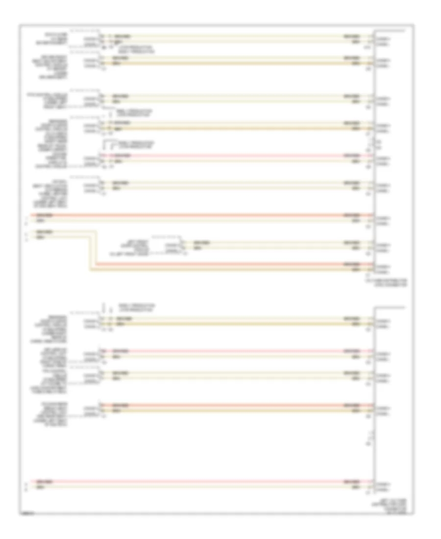
High/Low Bus Wiring Diagram (2 of 3) for Mercedes-Benz ML350 2008
List of elements for High/Low Bus Wiring Diagram (2 of 3) for Mercedes-Benz ML350 2008:
- Aac pushbutton control module (w/ aac (kla)) comfort aac pushbutton control module (w/ comfort aac (k-kla))
- C10
- C11
- Can-b h
- Can-b l
- Cockpit voltage distributor (can) connector
- Eis (ezs) control unit
- Electronic compass (if equipped) (behind instrument cluster)
- Front passenger front seat adjustment control module w/ memory (if equipped) (under front passenger's seat)
- Front sam control unit (under right front seat)
- Gl-class
- Instrument cluster
- Keyless go control unit (ml-class & if equipped) (right side of cargo area)
- Ml-class
- Overhead control panel control module
- Rcp (hbf) control module
- Rear sam control module (right rear of cargo area)
- Right front door control module (in right front door)
- Right voltage distributor (can) connector
- Tpm control module (ml-class & if equipped) (right side of cargo area)
- Upper control panel control module
- Wss control unit (weight sensing system) (ml-class: on right front seat frame) (gl-class: under front passenger's seat)
High/Low Bus Wiring Diagram (3 of 3) for Mercedes-Benz ML350 2008
List of elements for High/Low Bus Wiring Diagram (3 of 3) for Mercedes-Benz ML350 2008:
- C10
- Can-b h
- Can-b l
- Comand operating, display & control module
- Driver front seat adjustment control module w/ memory (under driver's seat)
- Dvd player (w/ rear entertainment)
- Early production
- Early production late production
- Folding rear bench seat control unit (3rd rear seat) (under left seat of 2nd row)
- Hs (sih), seat ventilation & steering wheel heater control unit (under left seat of 2nd seat row)
- Keyless go control unit (if equipped) (right side of cargo area)
- Late production
- Late production early production
- Left front door control module (in left front door)
- Left voltage distributor (can) connector (gl-class)
- Pts control module (if equipped) (under left front seat)
- Rear-end door closing control module (if equipped) (under right rear of cargo area floor)
- Rear-end door closing control module (ml-class & if equipped) (right rear rear of trunk, under carpet)
- Tpm control module (if equipped) (attached to load compartment fuse & relay box)
- Voltage distributor (can) connector