CRUISE CONTROL
Cruise Control Wiring Diagram for Mercedes-Benz SLK350 2014
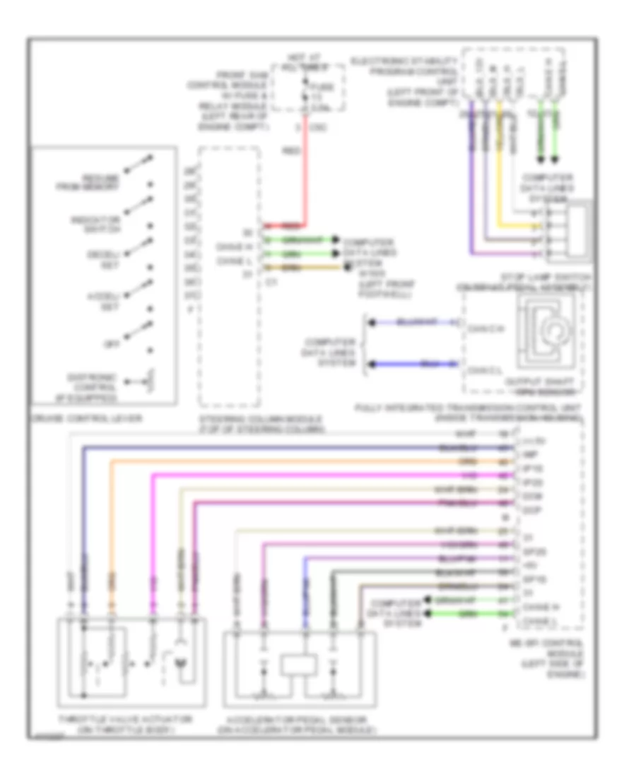
List of elements for Cruise Control Wiring Diagram for Mercedes-Benz SLK350 2014:
- (+) 5v
- +5v
- Accel/ set
- Accelerator pedal sensor (on accelerator pedal module)
- Bls_12v
- Bls_h
- Bls_l
- Bls_m
- C5c
- Can c h
- Can c l
- Can e h
- Can e l
- Can-e h
- Can-e l
- Computer data lines system
- Cruise control lever
- Dcm
- Dcp
- Decel/ set
- Distronic control (if equipped)
- Electronic stability program control unit (left front of engine compt)
- Front sam control module w/ fuse & relay module (left rear of engine compt)
- Fully integrated transmission control unit (inside transmission housing)
- Fuse 7.5a
- Hot at all times
- Imp
- Indicator switch
- Ip1s
- Ip2s
- Me-sfi control module (left side of engine)
- Off
- Output shaft rpm sensor
- Red
- Resume from memory
- Sp1s
- Sp2s
- Steering column module (top of steering column)
- Stop lamp switch (on brake pedal assembly)
- Throttle valve actuator (on throttle body)
- W15/5 (left front footwell)
 English