ENGINE PERFORMANCE
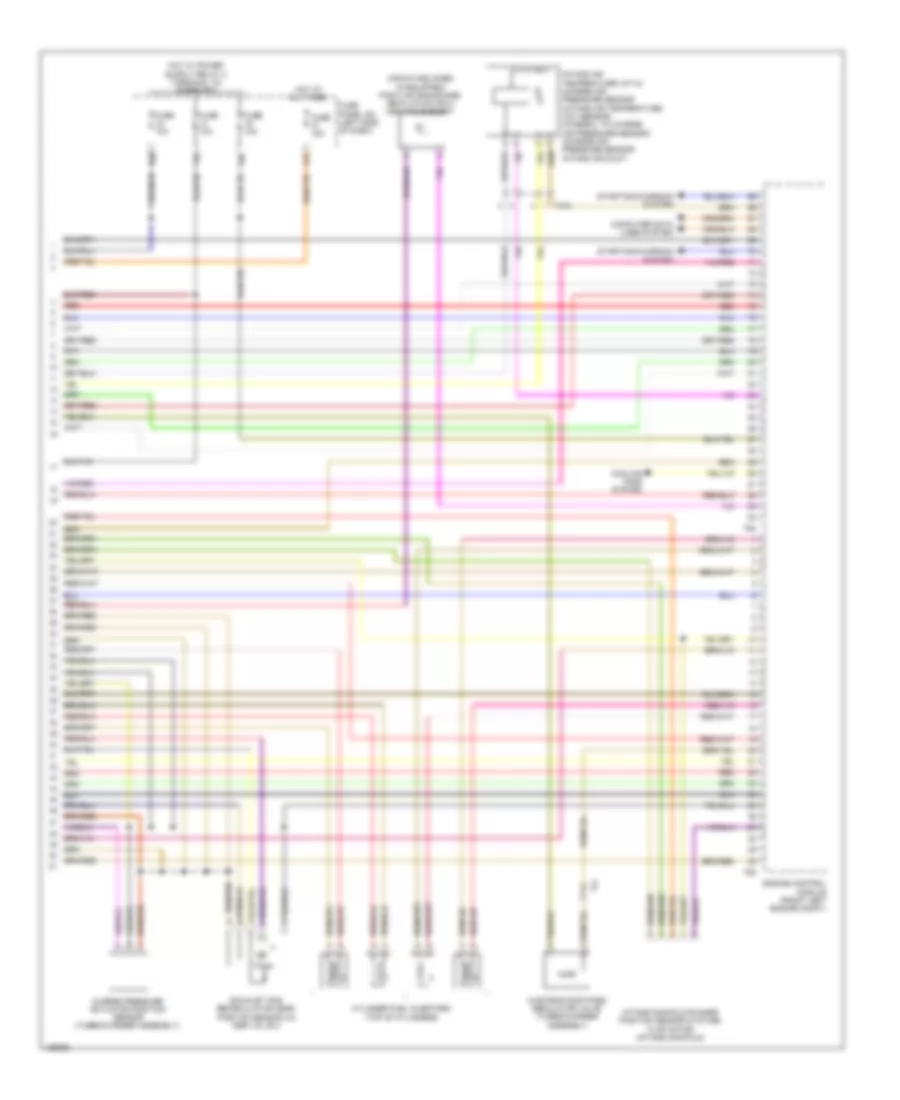
1.4L TURBO HYBRID
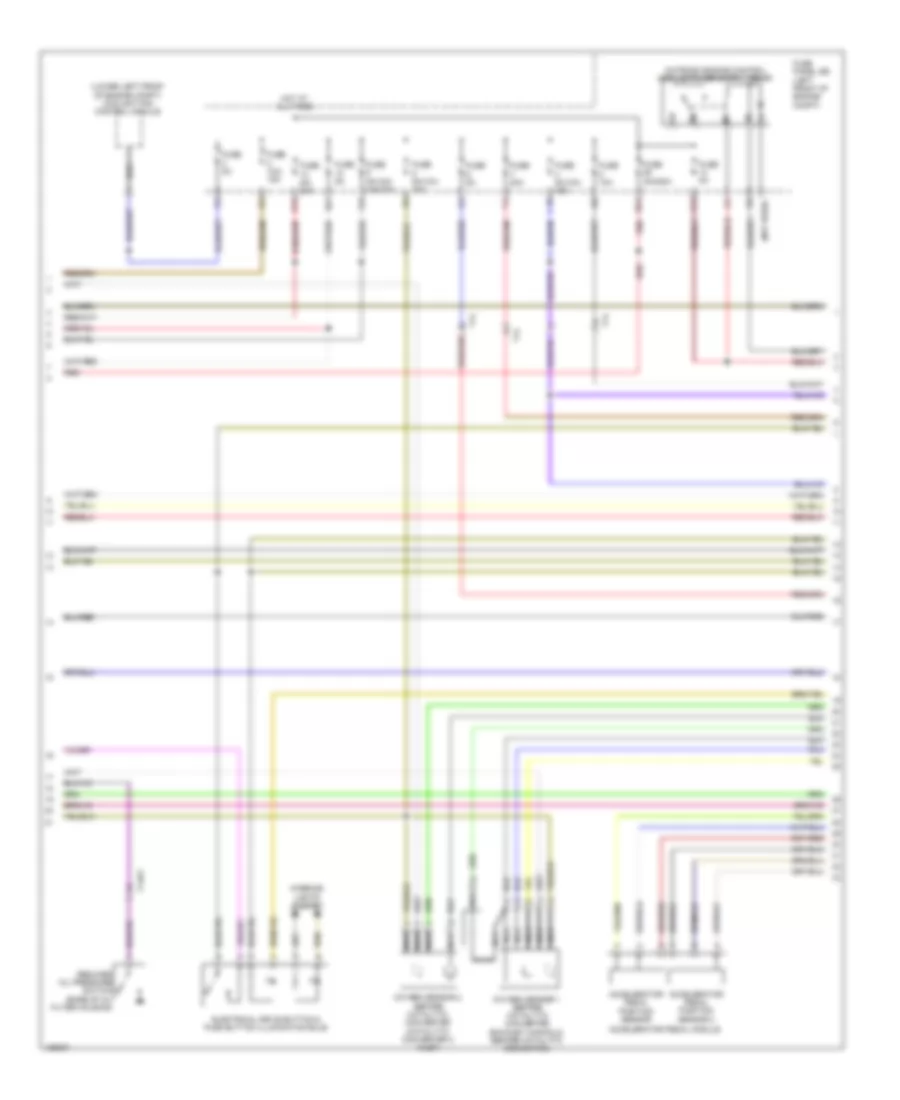
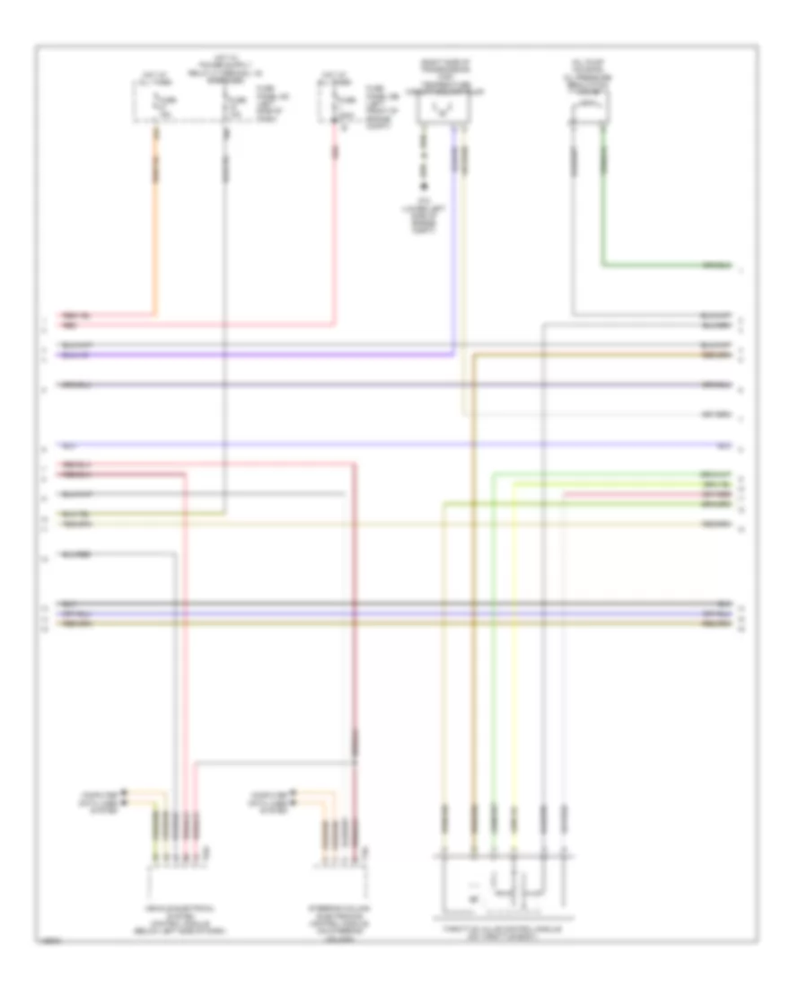
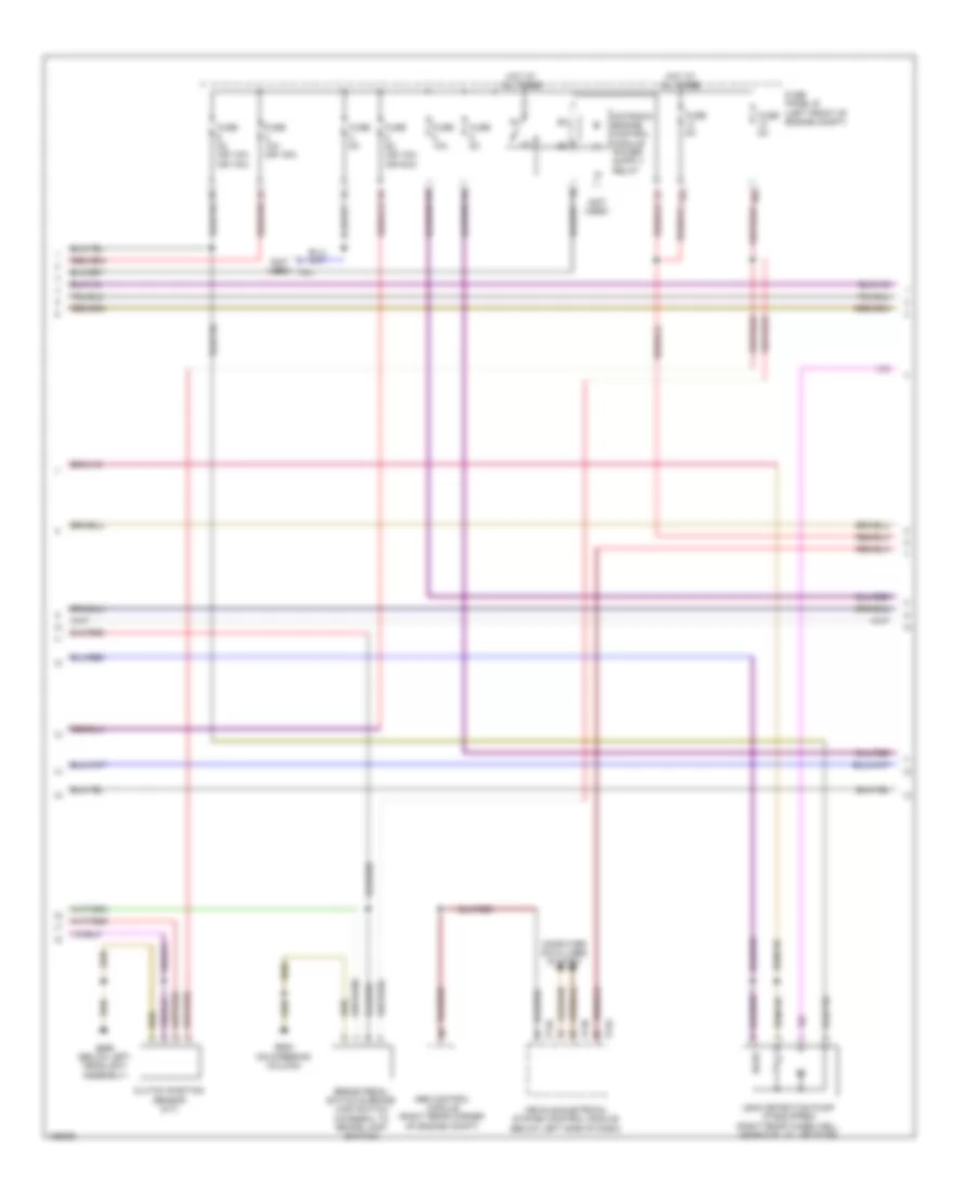
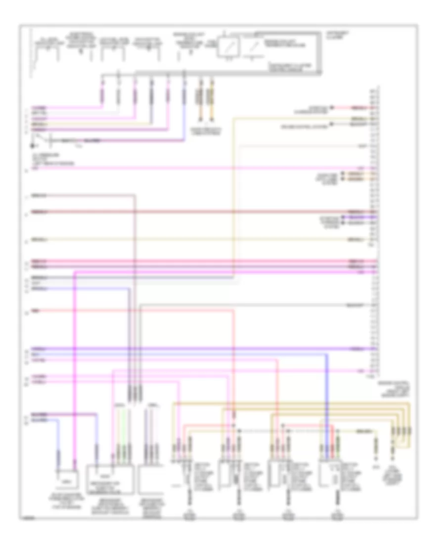
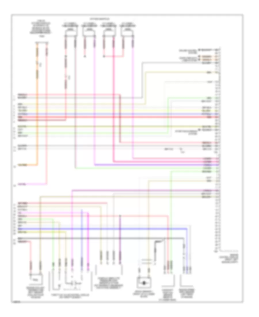
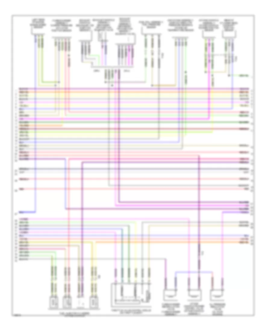
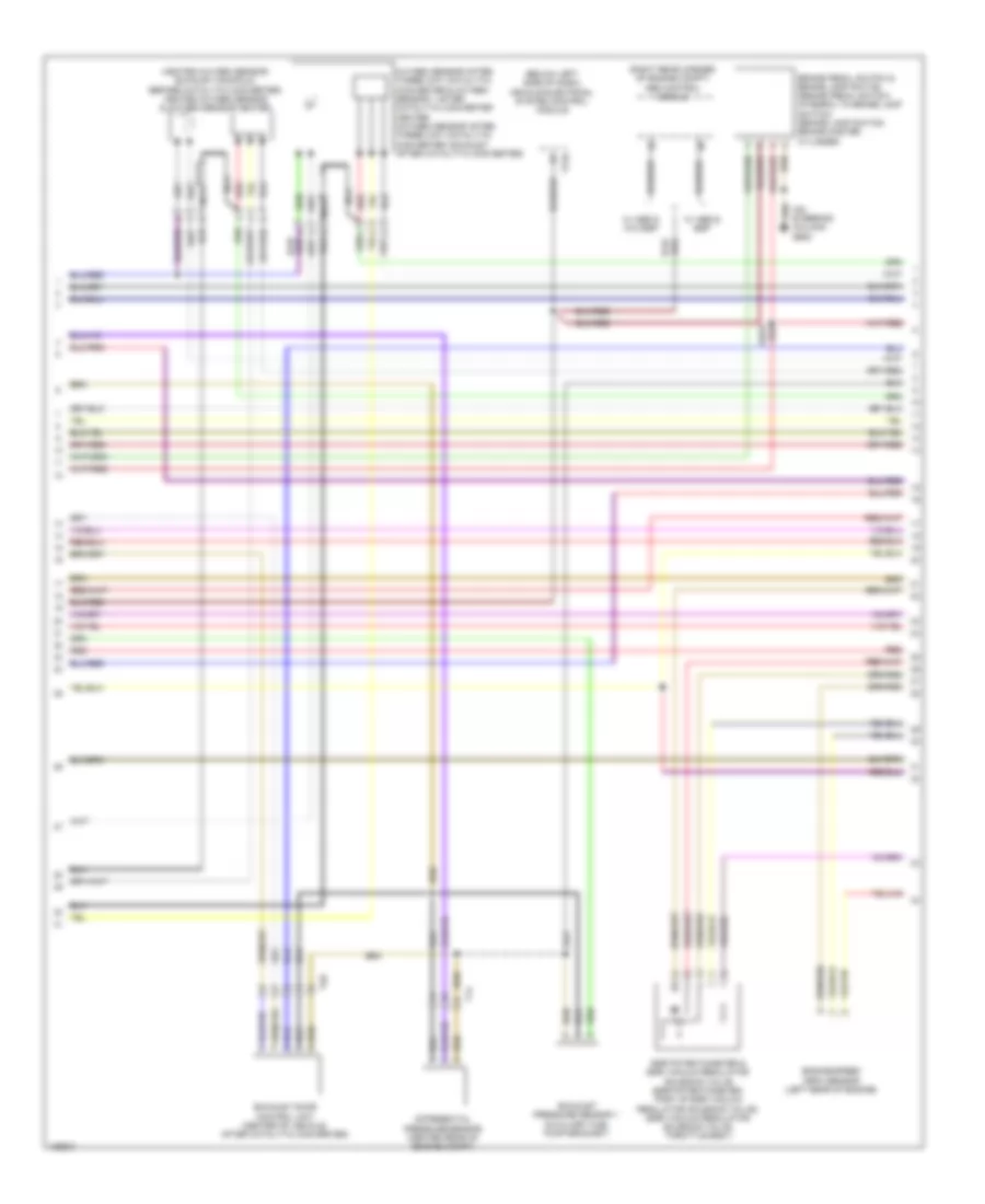
1.4L Turbo Hybrid, Engine Performance Wiring Diagram (1 of 8) for Volkswagen Jetta S 2014

List of elements for 1.4L Turbo Hybrid, Engine Performance Wiring Diagram (1 of 8) for Volkswagen Jetta S 2014:
- (below left headlight assembly) g655
- (if equipped) brake booster relay
- (intake air duct) charge air pressure sensor/ intake air temperature sensor 2
- (integral to brake lamp switch) brake pedal switch
- (lower left side of engine compt) g12
- (lower left side of engine) secondary air injection pump motor
- (relay carrier on electronics box) secondary air injection pump relay
- (right side of transmission) brake system vacuum pump
- Abs control module (right rear corner of engine compt)
- Brake booster pressure sensor (left rear of engine compt)
- Cooling fans system
- Engine control module (front left engine compt)
- Engine coolant temperature sensor (radiator outlet) (lower left corner of radiator)
- Evap canister purge regulator valve 2
- Fuel tank pressure sensor (fuel rail assembly)
- G12 (lower left side of engine compt)
- G44 (lower left "a" pillar)
- Leak detection pump (right rear wheelwell, near fuel filler door)
- Nca
- Oxygen sensor 1 after catalytic converter (catalytic converter 2 outlet)
- Red
- T14
- T14hy
- T2kh
- T94
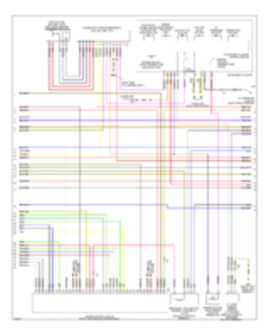
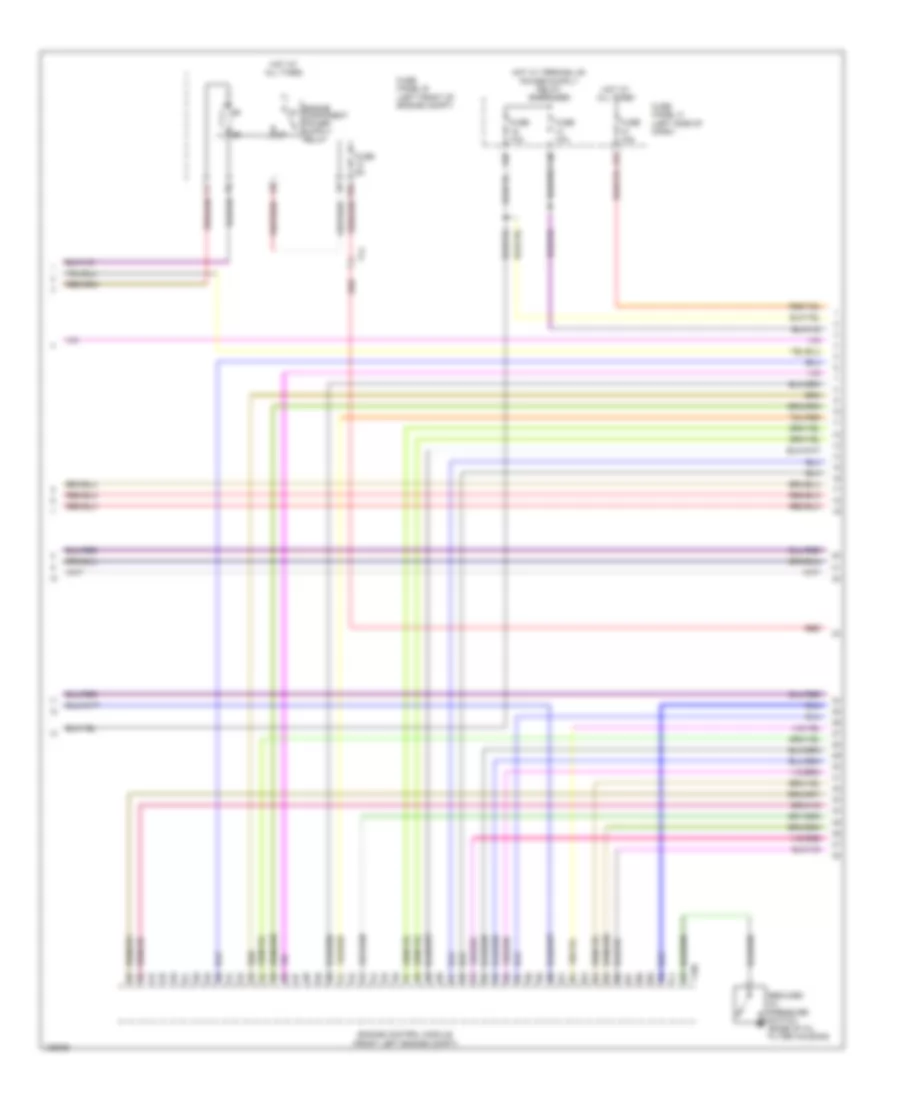
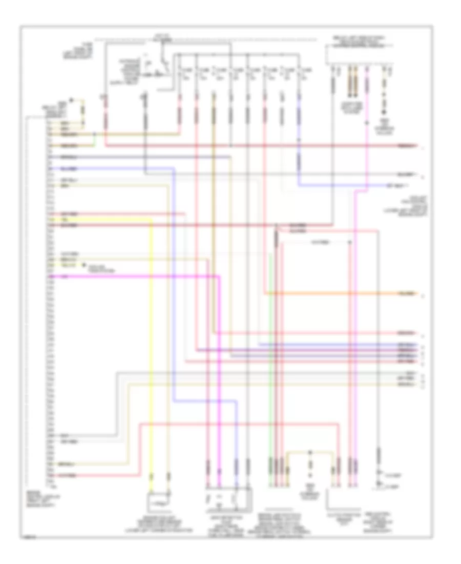
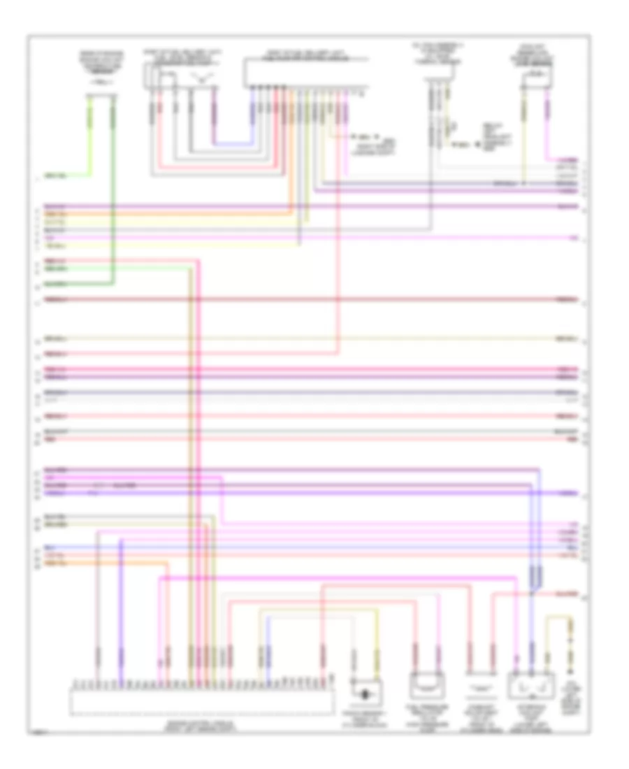
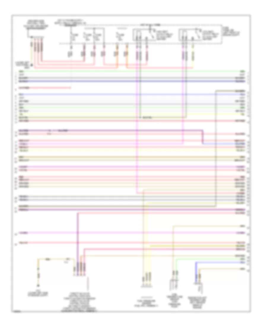
1.4L Turbo Hybrid, Engine Performance Wiring Diagram (2 of 8) for Volkswagen Jetta S 2014
List of elements for 1.4L Turbo Hybrid, Engine Performance Wiring Diagram (2 of 8) for Volkswagen Jetta S 2014:
- (lower left front of engine compt) coolant fan control module
- (not used)
- 10a
- 13a
- 14a
- 26a
- Accelerator pedal module
- Accelerator pedal position sensor
- Accelerator pedal position sensor 2
- Electrical drive button & push button illumination bulb
- Fuse 10a
- Fuse 10a/ 15a
- Fuse 20a
- Fuse 40a/50a
- Fuse 5a
- Fuse 5a/ 20a
- Fuse 5a/10a/ 15a
- Fuse 5a/10a/ 15a/20a
- Fuse 5a/10a/ 20a
- Fuse panel sb (left front of engine compt)
- Hot at all times
- Interior lights system
- Nca
- Oxygen sensor 1 before catalytic converter (exhaust manifold, before catalytic converter)
- Oxygen sensor 2 before catalytic converter (catalytic converter 2 inlet)
- Red
- Reduced oil pressure switch (base of oil filter housing)
- T14
- T14hy
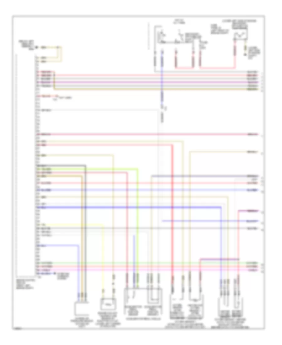
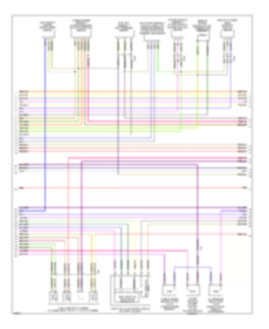
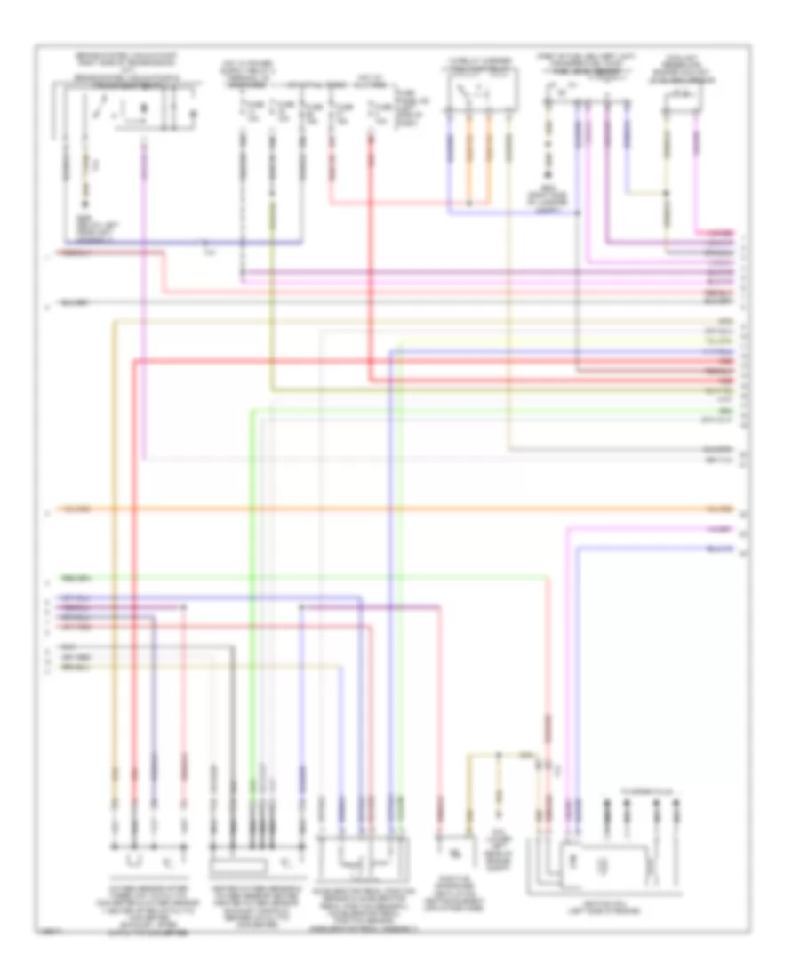
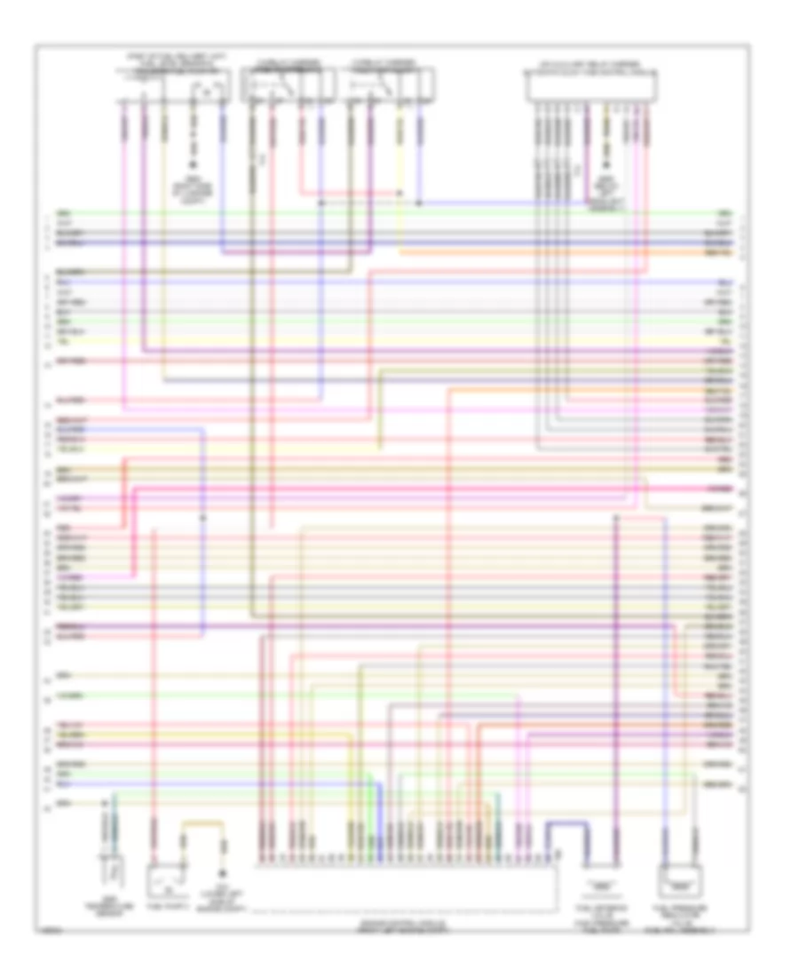
1.4L Turbo Hybrid, Engine Performance Wiring Diagram (3 of 8) for Volkswagen Jetta S 2014
List of elements for 1.4L Turbo Hybrid, Engine Performance Wiring Diagram (3 of 8) for Volkswagen Jetta S 2014:
- (lower left "a" pillar) g44
- (part of fuel delivery unit) fuel level sensor/ transfer fuel pump
- (right side of luggage compt)
- (under right side of rear seat) fuel delivery unit
- Computer data lines system
- Data lines computer
- Electronic power control malfunction indicator lamp
- Engine control module (front left engine compartment)
- Engine coolant level sensor (coolant reservoir)
- Engine coolant level/temperature indicator lamp
- Engine coolant temperature gauge
- Engine electronics indicator lamp
- Fuel gauge
- G655 (below left headlight assembly)
- G682
- Generator ind lamp
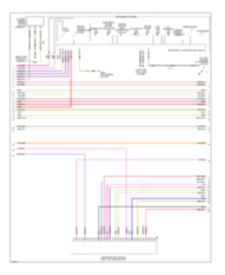
- Instrument cluster
- Instrument cluster control module
- Low fuel level ind lamp
- Malfunction ind lamp
- Oil level thermal sensor (w/ flexible service interval reminder) (oil pan assembly)
- Oil pressure ind lamp
- Oil pressure switch (right side of engine)
- Red
- Secondary air injection sensor 1 & solenoid valve (exhaust manifold assembly)
- System
- System data lines computer
- T14
- T6z
- T94
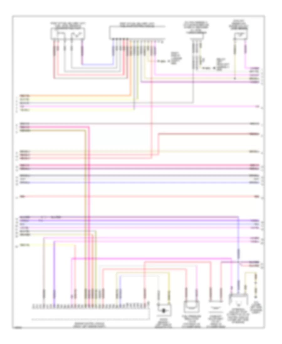
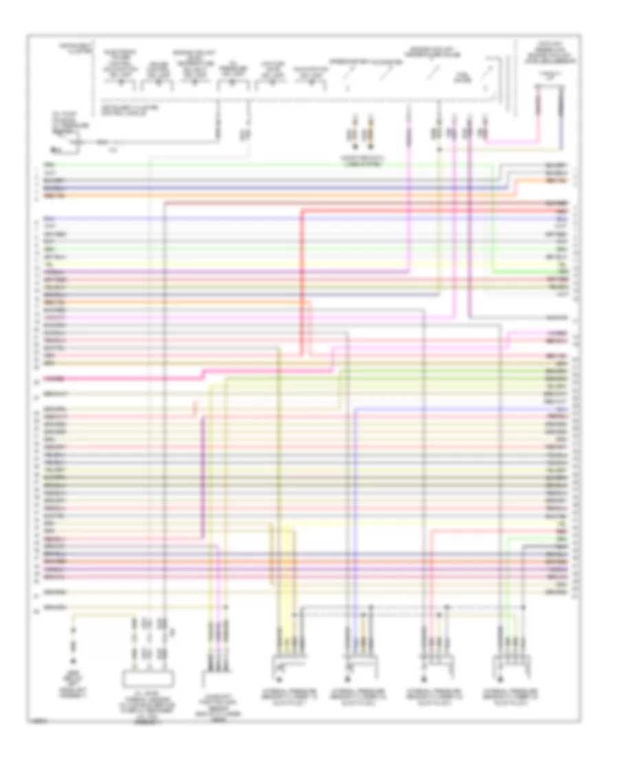
1.4L Turbo Hybrid, Engine Performance Wiring Diagram (4 of 8) for Volkswagen Jetta S 2014
List of elements for 1.4L Turbo Hybrid, Engine Performance Wiring Diagram (4 of 8) for Volkswagen Jetta S 2014:
- (left front of engine) low temperature circuit coolant pump
- 13b
- 14b
- 56a
- 56b
- 59a
- 59b
- Battery fan 1
- Battery fuse panel terminal 30 wire junction
- C1s
- Computer data lines system
- D1s
- Fan activation relay
- Fuel pressure regulator valve (left rear of engine)
- Fuse 10a
- Fuse 15a
- Fuse 5a
- Fuse 80a b1a
- Fuse panel sc (left side of dash)
- G12 (lower left side of engine compt)
- G662 (left side of luggage compt)
- G701
- High voltage system fuse
- High voltage system maintenance connector
- Hot at all times
- Hybrid battery unit (luggage compt)
- Nca
- Pilot line connector 1
- Red
- T14ax
- T4lh
- T8ax
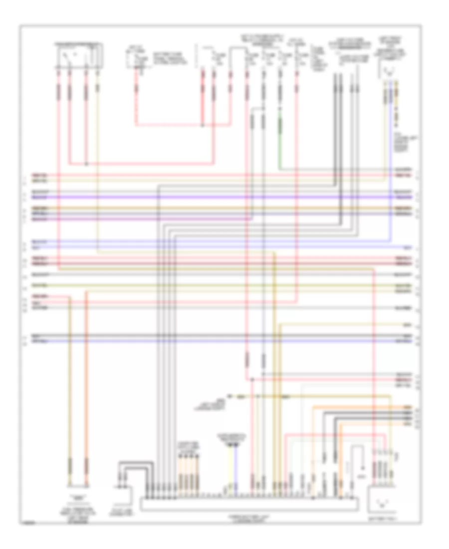
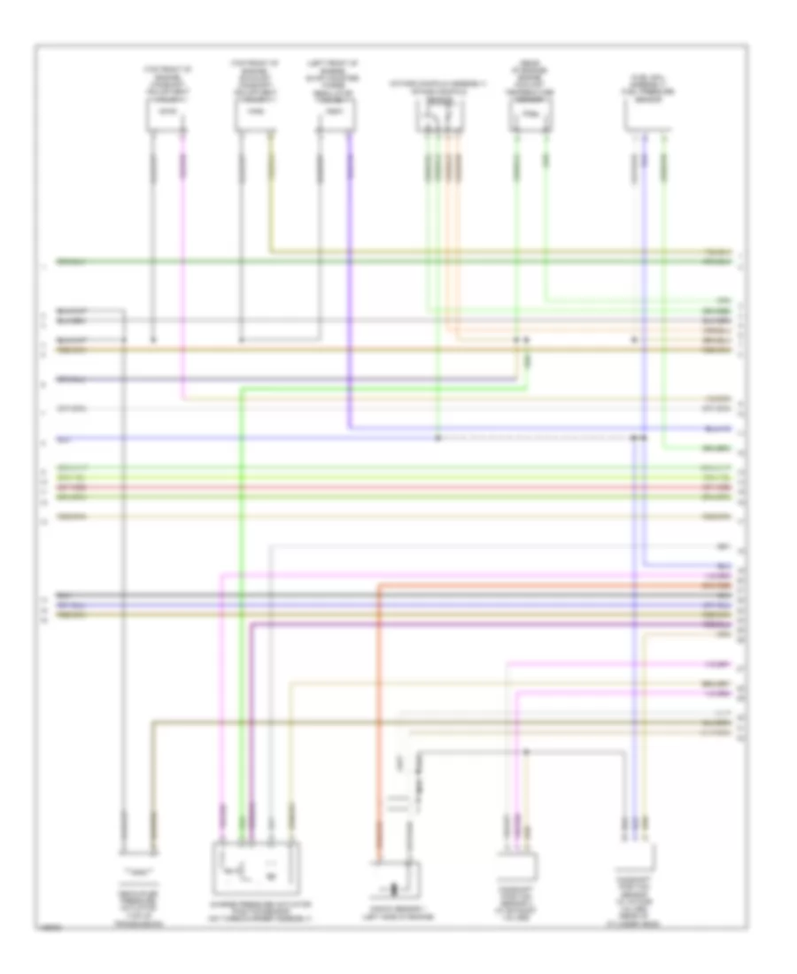
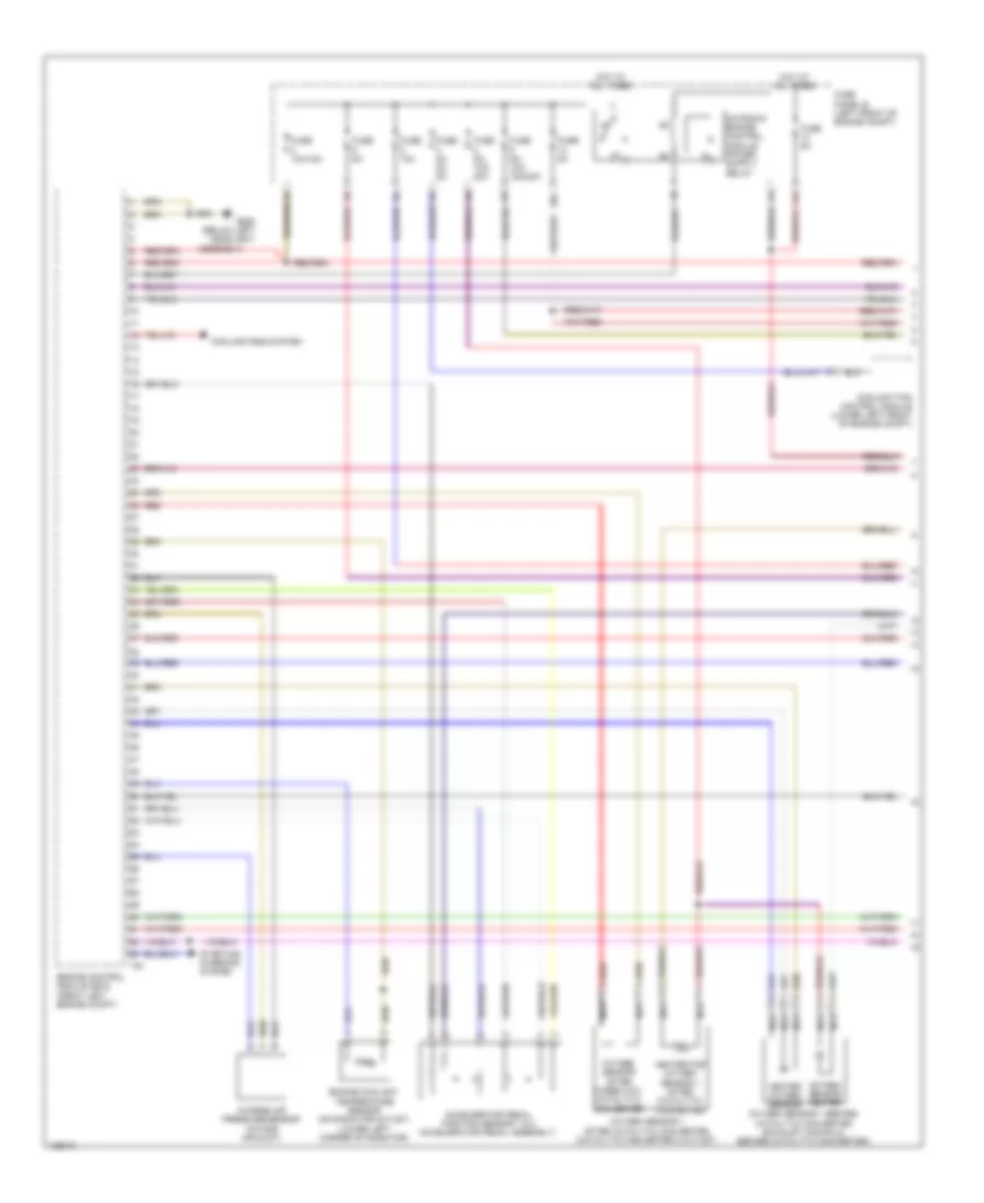
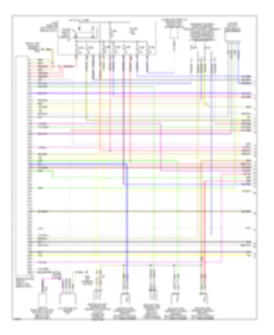
1.4L Turbo Hybrid, Engine Performance Wiring Diagram (5 of 8) for Volkswagen Jetta S 2014
List of elements for 1.4L Turbo Hybrid, Engine Performance Wiring Diagram (5 of 8) for Volkswagen Jetta S 2014:
- (center of dash) climatronic control module
- (electric air conditioner compressor) a/c compressor control module
- (left side of transmission) three-phrase current drive
- B1s
- C1s
- Computer data lines system
- D1s
- D2s
- E1s
- E2s
- E3s
- Electric drive power & control electronics
- G12 (lower left side of engine compt)
- G655 (below left headlight assembly)
- Nca
- Red
- T14hy
- T20c
- T28jx
- T2va
- T2vx
- T4bk
- T4hy
- T4jx
- T4vx
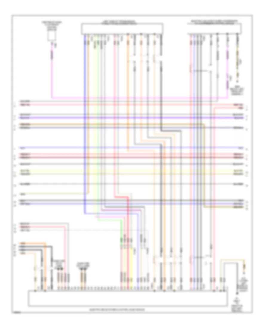
1.4L Turbo Hybrid, Engine Performance Wiring Diagram (6 of 8) for Volkswagen Jetta S 2014
List of elements for 1.4L Turbo Hybrid, Engine Performance Wiring Diagram (6 of 8) for Volkswagen Jetta S 2014:
- (oil pump housing) oil pressure regulation valve
- (right side of transmission) high temperature circuit coolant pump
- 16b
- 47b
- Computer data lines system
- Fuse 10a
- Fuse 15a
- Fuse 200a
- Fuse panel sb (left front of engine compt)
- Fuse panel sc (left side of dash)
- G12 (lower left side of engine compt)
- Hot at all times
- Red
- Steering column electronics control module (on steering column)
- T16l
- T52c
- Throttle valve control module (on throttle body)
- Vehicle electrical system control module (below left side of dash)
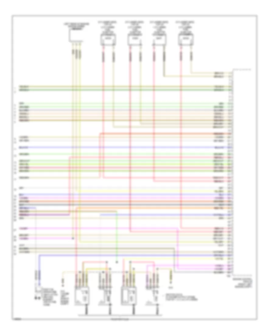
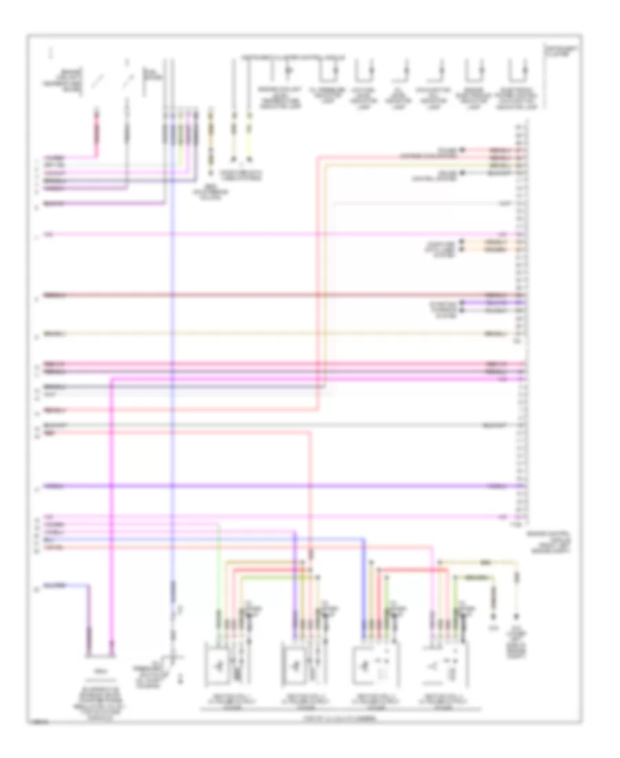
1.4L Turbo Hybrid, Engine Performance Wiring Diagram (7 of 8) for Volkswagen Jetta S 2014
List of elements for 1.4L Turbo Hybrid, Engine Performance Wiring Diagram (7 of 8) for Volkswagen Jetta S 2014:
- (fuel rail assembly) fuel pressure sensor
- (intake manifold assembly)
- (left front of engine) evap canister purge regulator valve 1
- (rear of engine) engine coolant temperature sensor
- (top front of engine) camshaft adjustment valve 1
- (top front of engine) exhaust camshaft adjustment valve 1
- Camshaft position sensor (w/ intake valves) (rear of cylinder head)
- Camshaft position sensor 3 (w/ exhaust valves)
- Charge pressure actuator position sensor (on turbocharger assembly)
- Decoupler pressure actuator (top of transmission)
- Intake manifold sensor
- Knock sensor 1 (left side of engine)
- Nca
1.4L Turbo Hybrid, Engine Performance Wiring Diagram (8 of 8) for Volkswagen Jetta S 2014
List of elements for 1.4L Turbo Hybrid, Engine Performance Wiring Diagram (8 of 8) for Volkswagen Jetta S 2014:
- (cylinder head, top of 1 cylinder) fuel injector cylinder 1
- (cylinder head, top of 2 cylinder) fuel injector cylinder 2
- (cylinder head, top of 3 cylinder) fuel injector cylinder 3
- (cylinder head, top of 4 cylinder) fuel injector cylinder 4
- (left rear of engine) engine speed sensor
- Engine control module (front left engine compt)
- G12 (lower left side of engine compt)
- G15
- Ignition coils w/ power output stage (top of 1, 2, 3, & 4 cylinder)
- Nca
- Positive crankcase ventilation heating element (air intake hose)
- T60
- To spark plug
1.8L TURBO
1.8L Turbo, Engine Performance Wiring Diagram (1 of 6) for Volkswagen Jetta S 2014
List of elements for 1.8L Turbo, Engine Performance Wiring Diagram (1 of 6) for Volkswagen Jetta S 2014:
- (below left headlight assembly) g655
- (lower left side of engine compt) g12
- (lower left side of engine) secondary air injection pump motor
- (not used) t4x
- 21a
- Accelerator pedal module
- Accelerator pedal position sensor
- Accelerator pedal position sensor 2
- Charge air pressure sensor (intake air duct)
- Engine control module (front left engine compt)
- Engine coolant temperature sensor on radiator outlet (lower left corner of radiator)
- Fuse 50a
- Fuse panel b (left front of engine compt)
- Heated oxygen sensor
- Heater for oxygen sensor 1 after catalytic converter
- Hot at all times
- Nca
- Oxygen sensor 1 after catalytic converter (catalytic converter 2 outlet)
- Oxygen sensor 1 before catalytic converter (exhaust manifold, before catalytic converter)
- Oxygen sensor after three way catalytic converter
- Oxygen sensor heater
- Red
- Secondary air injection pump relay
- Starting/ charging system
- T14
- T91
1.8L Turbo, Engine Performance Wiring Diagram (2 of 6) for Volkswagen Jetta S 2014
List of elements for 1.8L Turbo, Engine Performance Wiring Diagram (2 of 6) for Volkswagen Jetta S 2014:
- (not used)
- 10a
- 14a
- Abs control module (right rear corner of engine compt)
- Brake pedal switch & brake lamp switch (integral to brake lamp switch)
- Clutch position sensor (m/t)
- Computer data lines system
- Fuse 10a
- Fuse 10a (or 15a)
- Fuse 5a
- Fuse 5a (or 10a) (or 15a)
- Fuse 5a (or 10a) (or 20a)
- Fuse panel b (left front of engine compt)
- G605 (on steering column)
- G655 (below left headlight assembly)
- Hot at all times
- Leak detection pump (if equipped) (right rear wheelwell, near fuel filler door)
- T4x
- T73a
- T73b
- Vehicle electrical system control module (below left side of dash)
1.8L Turbo, Engine Performance Wiring Diagram (3 of 6) for Volkswagen Jetta S 2014
List of elements for 1.8L Turbo, Engine Performance Wiring Diagram (3 of 6) for Volkswagen Jetta S 2014:
- 12a
- 14b
- 16b
- 47b
- Engine control module (front left engine compt)
- Fuse 10a
- Fuse 15a
- Fuse 5a
- Fuse panel b (left front of engine compt)
- Fuse panel c (left side of dash)
- Hot at all times
- Red
- Reduced oil pressure switch (base of oil filter housing)
- T105
- T14
1.8L Turbo, Engine Performance Wiring Diagram (4 of 6) for Volkswagen Jetta S 2014
List of elements for 1.8L Turbo, Engine Performance Wiring Diagram (4 of 6) for Volkswagen Jetta S 2014:
- (air intake assembly) manifold absolute pressure sensor & intake manifold/air temperature sensor
- (end of cylinder head) camshaft position sensor
- (fuel rail assembly) fuel pressure sensor
- (intake manifold assembly) intake manifold runner position sensor
- (left rear of engine) engine speed sensor
- (rear of engine) engine coolant temperature sensor
- (turbocharger assembly) charge pressure actuator position sensor
- Drive epc throttle
- Epc throttle drive angle sensor 1 & 2
- Fuel injector cylinders (cylinder head, top of 1, 2, 3 & 4 cylinders)
- Intake manifold runner control valve (intake manifold assembly)
- Oil pressure regulation valve (base of block, near a/c compressor)
- Red
- Sensor 1
- Sensor 2
- T14
- T14a
- T8i
- Throttle valve control module (on throttle body)
- Turbocharger recirculation valve (turbocharger assembly)
1.8L Turbo, Engine Performance Wiring Diagram (5 of 6) for Volkswagen Jetta S 2014
List of elements for 1.8L Turbo, Engine Performance Wiring Diagram (5 of 6) for Volkswagen Jetta S 2014:
- (below left headlight assembly) g655
- (coolant reservoir) engine coolant level sensor
- (oil pan assembly) (w/ flexible service interval reminder) oil level thermal sensor
- (part of fuel delivery unit) fuel level sensor & transfer fuel pump
- (part of fuel delivery unit) fuel pump control module
- (right side of luggage compt) g682
- After-run coolant pump & throttle valve control module (lower left side of engine)
- Camshaft adjustment valve 1 (front of cylinder head)
- Engine control module (front left engine compt)
- Fuel pressure regulator valve (top front of cylinder head)
- G12 (lower left side of engine compt)
- Knock sensor 1 (left side of engine block)
- Red
- T105
- T14
- T6z
1.8L Turbo, Engine Performance Wiring Diagram (6 of 6) for Volkswagen Jetta S 2014
List of elements for 1.8L Turbo, Engine Performance Wiring Diagram (6 of 6) for Volkswagen Jetta S 2014:
- Computer data lines system
- Computer data lines systems
- Cpka
- Cpra
- Cruise control system
- Electronic power control malfunction indicator lamp
- Engine control module (front left engine compt)
- Engine coolant level/ temperature indicator
- Engine coolant temperature gauge
- Evap canister purge regulator valve 1 (top of engine)
- Fuel gauge
- G12 (lower left side of engine compt)
- G15
- Ignition coil 1 w/ power output stage (top of 1 cylinder)
- Ignition coil 2 w/ power output stage (top of 2 cylinder)
- Ignition coil 3 w/ power output stage (top of 3 cylinder)
- Ignition coil 4 w/ power output stage (top of 4 cylinder)
- Instrument cluster
- Instrument cluster control module
- Low fuel level indicator lamp
- Malfunction indicator lamp
- Nca
- Oil level indicator lamp
- Oil pressure switch (left rear of engine)
- Red
- Secondary air injection sensor 2 (exhaust manifold)
- Secondary air injection solenoid valve
- Secondary air system & injection sensor 1 (exhaust manifold)
- Starting/ charging system
- T105
- T14
- T91
- To spark plug
2.0L
2.0L, Engine Performance Wiring Diagram (1 of 4) for Volkswagen Jetta S 2014
List of elements for 2.0L, Engine Performance Wiring Diagram (1 of 4) for Volkswagen Jetta S 2014:
- (below left side of dash) vehicle electrical system control module
- (or 61)
- (or 62)
- 10a
- 14a
- Abs control module (right rear of corner engine compt)
- Brake lamp switch & brake pedal switch (brake lamp switch: brake master cylinder) (brake pedal switch: integral to brake lamp switch)
- Clutch position sensor (m/t)
- Computer data lines system
- Coolant fan control module (lower left front of engine compt)
- Cooling fans system
- Engine control module (front left engine compt)
- Engine coolant temperature sensor (on radiator outlet) (lower left corner of radiator)
- Fuse 10a
- Fuse 15a
- Fuse 20a
- Fuse 5a
- Fuse panel sb (left front of engine compt)
- G605 (on steering column)
- G655 (below left headlight assembly)
- Hot at all times
- Leak detection pump (right rear wheelwell, near fuel filler door)
- T73a
- T73b
- T94
- W/ esp
- W/o esp
2.0L, Engine Performance Wiring Diagram (2 of 4) for Volkswagen Jetta S 2014
List of elements for 2.0L, Engine Performance Wiring Diagram (2 of 4) for Volkswagen Jetta S 2014:
- (12-relay carrier) fuel pump relay
- (brake system vacuum pump: right side of transmission) (a/t) brake system vacuum pump & vacuum pump relay
- (coolant reservoir) engine coolant level (ecl) sensor
- (part of fuel delivery unit) transfer fuel pump/ fuel level sensor
- 14b
- 16b
- 26b
- 47b
- Accelerator pedal position sensor & accelerator pedal position sensor 2 (accelerator pedal position sensor: accelerator pedal assembly)
- Fuse 10a
- Fuse 15a
- Fuse panel sc (left side of dash)
- G12 (lower left rear of engine compt)
- G655 (below left headlight assembly)
- G682 (right side of luggage compt)
- Heated oxygen sensor & oxygen sensor heater (heated oxygen sensor: exhaust manifold, before catalytic converter)
- Hot at all times
- Ignition coil (left side of engine)
- Nca
- Oxygen sensor after three way catalytic converter & oxygen sensor 1 heater after catalytic converter (exhaust, after catalytic converter)
- Positive crankcase ventilation heating element (air intake hose)
- Red
- T14
- T44
- T4y
- To spark plug
2.0L, Engine Performance Wiring Diagram (3 of 4) for Volkswagen Jetta S 2014
List of elements for 2.0L, Engine Performance Wiring Diagram (3 of 4) for Volkswagen Jetta S 2014:
- (below left headlight assembly)
- (oil pump housing) oil pressure switch
- Computer data lines system
- Cruise control ind lamp
- Electronic power control malfunction ind lamp
- Engine control module (front left engine compt)
- Engine coolant level/ temperature ind lamp
- Engine coolant temperature gauge
- Fuel gauge
- G605 (on steering column)
- G655
- Generator ind lamp
- Instrument cluster
- Instrument cluster control module
- Low fuel ind lamp
- Malfunction ind lamp
- Oil level thermal sensor (oil pan assembly)
- Oil pressure ind lamp
- Red
- Speedometer
- T14
- T60
- T6z
- Tachometer
- Warning buzzer & tone
2.0L, Engine Performance Wiring Diagram (4 of 4) for Volkswagen Jetta S 2014
List of elements for 2.0L, Engine Performance Wiring Diagram (4 of 4) for Volkswagen Jetta S 2014:
- (intake manifold)
- (top of intake manifold) evaporative emission (evap) canister purge regulator valve 1
- Camshaft position sensor (rear of cylinder head)
- Computer data lines system
- Cruise control system
- Cylinder 1 fuel injector
- Cylinder 2 fuel injector
- Cylinder 3 fuel injector
- Cylinder 4 fuel injector
- Engine control module (front left engine compt)
- Engine coolant temperature (ect) sensor (coolant pump housing)
- Engine speed (rpm) sensor (left rear of engine)
- Knock sensor 1 (front of cylinder block)
- Manifold absolute pressure (map) sensor & intake air temperature sensor (air intake assembly)
- Red
- Starting/charging system
- T14
- T4y
- T60
- T94
- Throttle valve control module (on throttle body)
2.0L TURBO
2.0L Turbo, Engine Performance Wiring Diagram (1 of 6) for Volkswagen Jetta S 2014
List of elements for 2.0L Turbo, Engine Performance Wiring Diagram (1 of 6) for Volkswagen Jetta S 2014:
- 10a
- 14a
- Accelerator pedal position sensor 1 & 2 (accelerator pedal assembly)
- Assembly)
- Charge air pressure sensor (intake air duct)
- Coolant fan control module (lower left front of engine compt)
- Cooling fans system
- Engine control module (ecm) (front left engine compt)
- Engine coolant temperature sensor (on radiator outlet) (lower left corner of radiator)
- Fuse 10a
- Fuse 10a/15a
- Fuse 5a
- Fuse 5a 5a 5a
- Fuse 5a/ 10a/ 15a/20a
- Fuse 5a/ 10a/ 20a
- Fuse panel b (left front of engine compt)
- G655 (below left headlight
- Heated oxygen sensor
- Heater for oxygen sensor 1 after catalytic converter
- Hot at all times
- Nca
- Oxygen sensor 1 after catalytic converter (catalytic converter 2 outlet)
- Oxygen sensor 1 before catalytic converter (exhaust manifold, before catalytic converter)
- Oxygen sensor after three way catalytic converter
- Oxygen sensor heater
- Red
- Starting/ charging system
- T91
2.0L Turbo, Engine Performance Wiring Diagram (2 of 6) for Volkswagen Jetta S 2014
List of elements for 2.0L Turbo, Engine Performance Wiring Diagram (2 of 6) for Volkswagen Jetta S 2014:
- (below left side of dash)
- (lower left side of engine)
- 21a
- Abs control
- Brake pedal switch/brake lamp switch (brake master cylinder)
- Clutch position sensor (m/t)
- Computer data lines system
- Fuse 50a
- Fuse panel b (left front of engine compt)
- G12 (lower left side of engine compt)
- G605 (on steering column)
- G655 (below left headlight assembly)
- Hot at all times
- Leak detection pump (if equipped) (right rear wheelwell, near fuel filler door)
- Module (right rear corner of engine compt)
- Secondary air injection pump motor
- Secondary air injection pump relay
- T14
- T52b
- T52c
- Vehicle electrical system control module
2.0L Turbo, Engine Performance Wiring Diagram (3 of 6) for Volkswagen Jetta S 2014
List of elements for 2.0L Turbo, Engine Performance Wiring Diagram (3 of 6) for Volkswagen Jetta S 2014:
- 12a
- 14b
- 16b
- 47b
- Engine control module (front left engine compt)
- Fuse 10a
- Fuse 15a
- Fuse 5a
- Fuse panel b (left front of engine compt)
- Fuse panel c (left side of dash)
- Hot at all times
- Red
- Reduced oil pressure switch (base of oil filter housing)
- T105
- T14
2.0L Turbo, Engine Performance Wiring Diagram (4 of 6) for Volkswagen Jetta S 2014
List of elements for 2.0L Turbo, Engine Performance Wiring Diagram (4 of 6) for Volkswagen Jetta S 2014:
- (air intake assembly) manifold absolute pressure sensor & intake air temperature sensor
- (exhaust manifold assembly) secondary air injection sensor 1/ solenoid valve
- (exhaust manifold assembly) secondary air injection solenoid valve
- (exhaust manifold) secondary air injection sensor 2
- (fuel rail assembly) fuel pressure sensor
- (intake manifold assembly) intake manifold runner position sensor
- (left rear of engine)
- (rear of cylinder head) camshaft position sensor
- (turbocharger assembly) charge pressure actuator position sensor
- Cpla
- Cppa
- Engine speed sensor
- Fuel injector cylinders (intake manifold)
- Intake manifold runner control valve (intake manifold assembly)
- Oil pressure regulation valve (oil pump housing)
- Red
- Sensor 1
- Sensor 2
- T14
- T14a
- T8i
- Throttle drive
- Throttle valve control module (on throttle body)
- Turbocharger recirculation valve (turbocharger assembly)
2.0L Turbo, Engine Performance Wiring Diagram (5 of 6) for Volkswagen Jetta S 2014
List of elements for 2.0L Turbo, Engine Performance Wiring Diagram (5 of 6) for Volkswagen Jetta S 2014:
- (below left headlight assembly) g655
- (coolant reservoir) engine coolant level sensor
- (oil pan assembly) (if equipped) oil level thermal sensor
- (part of fuel delivery unit) fuel level sensor & transfer fuel pump
- (part of fuel delivery unit) fuel pump (fp) control module
- (rear of engine)
- After-run coolant pump (lower left side of engine)
- Camshaft adjustment valve 1 (front of cylinder head)
- Engine control module (front left engine compt)
- Engine coolant temperature sensor
- Fuel pressure regulator valve (high pressure pump)
- G12 (lower left side of engine compt)
- G682 (right side of luggage compt)
- Knock sensor 1 (front of cylinder block)
- Red
- T105
- T14
- T6z
2.0L Turbo, Engine Performance Wiring Diagram (6 of 6) for Volkswagen Jetta S 2014
List of elements for 2.0L Turbo, Engine Performance Wiring Diagram (6 of 6) for Volkswagen Jetta S 2014:
- (top of 1,2, 3 & 4 cylinders)
- Computer data lines system
- Computer data lines systems
- Cruise control system
- Electronic power control malfunction indicator lamp
- Engine control module (front left engine compt)
- Engine coolant level/ temperature indicator lamp
- Engine coolant temperature gauge
- Engine electronics indicator lamp
- Evaporative emission (evap) canister purge regulator valve 1 (top of intake manifold)
- Fuel gauge
- G12 (lower left side of engine compt)
- G15
- G605 (on steering column)
- Ignition coil 1 w/ power output stage
- Ignition coil 2 w/ power output stage
- Ignition coil 3 w/ power output stage
- Ignition coil 4 w/ power output stage
- Instrument cluster
- Instrument cluster control module
- Low fuel level indicator lamp
- Malfunction (mil) indicator lamp
- Nca
- Oil level indicator lamp
- Oil pressure indicator lamp
- Oil pressure switch (oil pump housing)
- Power distribution system
- Red
- Starting/ charging system
- T105
- T14
- T91
- To spark plug
2.0L TURBO DIESEL
2.0L Turbo Diesel, Engine Performance Wiring Diagram (1 of 6) for Volkswagen Jetta S 2014
List of elements for 2.0L Turbo Diesel, Engine Performance Wiring Diagram (1 of 6) for Volkswagen Jetta S 2014:
- (accelerator pedal position sensor: accelerator pedal assembly) accelerator pedal position sensor 2 & accelerator pedal position sensor
- (below left headlight assembly) g655
- (intake air duct) mass airflow (maf) sensor
- (lower left front of engine compt) coolant fan control module
- (or 61)
- (or 62)
- 14a
- 26a
- Clutch position sensor (m/t)
- Cruise control system
- Engine control module (front left engine compt)
- Engine coolant temperature sensor (on radiator outlet) (lower left corner of radiator)
- Exhaust gas temperature (egt) sensor 2 (exhaust manifold, at turbocharger)
- Exhaust gas temperature (egt) sensor 3 (exhaust manifold, at turbocharger)
- Exhaust gas temperature (egt) sensor 4 (exhaust manifold, at turbocharger)
- Exhaust gas temperature sensor 1 (exhaust manifold,at turbocharger)
- Fuse 15a
- Fuse 5a
- Fuse 60a
- Fuse panel sb (left front of engine compt)
- G605 (on steering column)
- Hot at all times
- Red
- T14
- T73b
- T94
- Vehicle electrical system control module (below left side of dash)
2.0L Turbo Diesel, Engine Performance Wiring Diagram (2 of 6) for Volkswagen Jetta S 2014
List of elements for 2.0L Turbo Diesel, Engine Performance Wiring Diagram (2 of 6) for Volkswagen Jetta S 2014:
- (below left side of dash) vehicle electrical system control module
- (heated oxygen sensor: exhaust manifold, before catalytic converter) heated oxygen sensor & oxygen sensor heater
- (on steering column) g605
- (right rear corner of engine compt) abs control module
- Brake pedal switch & brake lamp switch (brake pedal switch: integral to brake lamp switch) (brake lamp switch: brake master cylinder)
- Differential pressure sensor (center rear of engine compt)
- Egr potentiometer & egr vacuum regulator solenoid valve (egr potentiometer: part of egr vacuum regulator solenoid valve) (egr vacuum regulator solenoid valve: throttle body)
- Engine speed (rpm) sensor (left rear of engine)
- Exhaust door control unit (center of vehicle, after catalytic converter)
- Exhaust pressure sensor 1 (auxiliary fuel pump bracket)
- Nca
- Oxygen sensor after three way catalytic converter & oxygen sensor 1 after catalytic converter heater (oxygen sensor after three way catalytic converter: exhaust, after catalytic converter)
- Red
- T14
- T5k
- T73a
- W/ abs & esp
- W/ abs & w/o esp
2.0L Turbo Diesel, Engine Performance Wiring Diagram (3 of 6) for Volkswagen Jetta S 2014
List of elements for 2.0L Turbo Diesel, Engine Performance Wiring Diagram (3 of 6) for Volkswagen Jetta S 2014:
- (driver's side footwell trim)
- (lower left kick panel) g602
- 10a
- 21a
- 22a
- 32a
- Auxiliary air heater heating element
- Engine coolant temperature (ect) sensor (rear of engine)
- Fuel pressure sensor (fuel rail assembly)
- Fuel temperature sensor (high pressure pump)
- Fuse 40a
- Fuse 50a
- Fuse 5a
- Fuse panel sb (left front of engine compt)
- G12 (lower left side of engine compt)
- High heat output relay (w/ auxiliary heater)
- Hot at all times
- Low heat output relay (w/ auxiliary heater)
- Red
- T14
- Throttle valve control module & throttle position sensor (throttle valve control module: on throttle body) (throttle position sensor: accelerator pedal assembly)
2.0L Turbo Diesel, Engine Performance Wiring Diagram (4 of 6) for Volkswagen Jetta S 2014
List of elements for 2.0L Turbo Diesel, Engine Performance Wiring Diagram (4 of 6) for Volkswagen Jetta S 2014:
- (12-relay carrier) fuel pump relay
- (12-relay carrier) fuel pump relay 2
- (on auxiliary relay carrier) automatic glow time control module
- (part of fuel delivery unit) fuel level sensor & transfer fuel pump (fp)
- Egr temperature sensor
- Engine control module (front left engine compt)
- Fuel metering valve (high pressure fuel pump)
- Fuel pressure regulator valve (fuel rail assembly)
- Fuel pump 2
- G12 (lower left side of engine compt)
- G655 (below left headlight assembly)
- G682 (right side of luggage compt)
- Red
- T14
- T60
2.0L Turbo Diesel, Engine Performance Wiring Diagram (5 of 6) for Volkswagen Jetta S 2014
List of elements for 2.0L Turbo Diesel, Engine Performance Wiring Diagram (5 of 6) for Volkswagen Jetta S 2014:
- (coolant reservoir) engine coolant level (ecl) sensor
- (oil pump housing) oil pressure switch
- Camshaft position (cmp) sensor (end of cylinder head)
- Computer data lines system
- Cruise control ind lamp
- Electronic power control malfunction ind lamp
- Engine coolant level/ temperature (ecl/ect) ind lamp
- Engine coolant temperature gauge
- Fuel gauge
- G655 (below left headlight assembly)
- Instrument cluster
- Instrument cluster control module
- Internal pressure sensor cylinder 1 & glow plug 1
- Internal pressure sensor cylinder 2 & glow plug 2
- Internal pressure sensor cylinder 3 & glow plug 3
- Internal pressure sensor cylinder 4 & glow plug 4
- Low fuel level ind lamp
- Malfunction ind lamp
- Nca
- Oil level thermal sensor (w/ flexible service interval reminder) (oil pan assembly)
- Oil pressure ind lamp
- Red
- Speedometer
- T14
- T6z
- Tachometer
2.0L Turbo Diesel, Engine Performance Wiring Diagram (6 of 6) for Volkswagen Jetta S 2014
List of elements for 2.0L Turbo Diesel, Engine Performance Wiring Diagram (6 of 6) for Volkswagen Jetta S 2014:
- (air intake hose) (if equipped) positive crankcase ventilation (pcv) heating element
- 14b
- 15b
- 16b
- 47b
- Charge pressure actuator position sensor (turbocharger assembly)
- Computer data lines system
- Cooling fans system
- Cylinder fuel injectors (top of cylinders)
- Engine control module (front left engine compt)
- Exhaust gas recirculation (egr) position sensor 2 & egr valve 2
- Fuse 10a
- Fuse 15a
- Fuse panel sc (left side of dash)
- Hot at all times
- Intake air temperature (iat) & charge air pressure sensor (intake air temperature (iat) sensor: integral to charge air pressure sensor) (charge air pressure sensor: intake air duct)
- Intake manifold runner position sensor & intake flap motor (intake manifold)
- Red
- Starting/charging system
- T14
- T4aj
- T60
- T94
- Wastegate bypass regulator valve (turbocharger assembly)