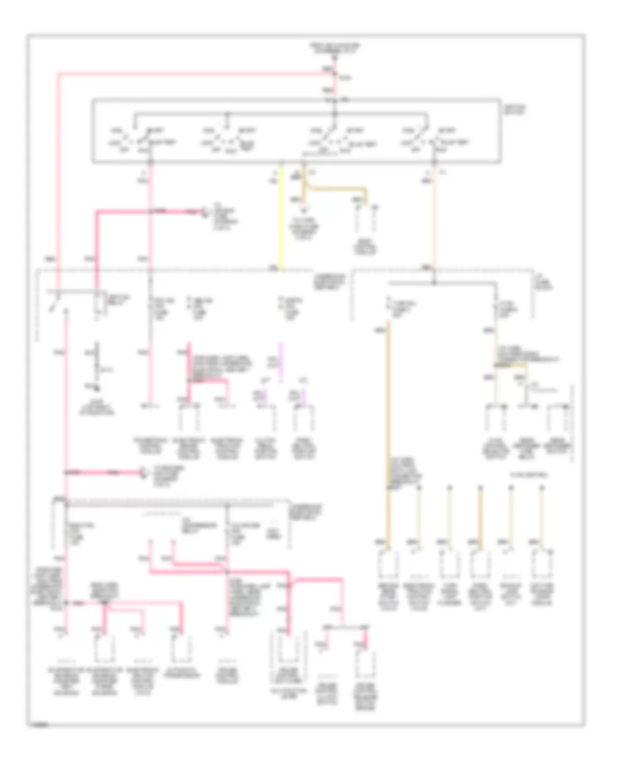
POWER DISTRIBUTION
Power Distribution Wiring Diagram (1 of 4) for Chevrolet Camaro 1998

List of elements for Power Distribution Wiring Diagram (1 of 4) for Chevrolet Camaro 1998:
- (eng harn, near powertrain control module) s106
- (forward lamp harn, 30cm from underhood electrical center 1 breakout)
- (forward lamp harn, 8cm from underhood electrical center 1 breakout) s168
- (forward lamp harn, left side of dash) s203
- A10
- Abs bat 1 maxi fuse 40a
- Abs bat 2 maxi fuse 40a
- Abs bat mini fuse 25a
- Air pump mini fuse 25a
- Air pump relay
- Air solenoid relay
- Battery
- Blower motor relay
- Body control module
- Cool fan 1 mini relay
- Cool fan 2 mini relay
- Cool fan 3 mini relay
- Cool fan maxi fuse 40a
- Cool fan mini fuse 10a
- Electronic brake control module
- Electronic traction control module
- Eng ctrl maxi fuse 40a
- Fuel pump mini fuse 20a
- Fuel pump relay
- Generator
- Headlamp opening actuator control module
- Headlamp switch
- Hl door-horn maxi fuse 50a
- Horn mini fuse 20a
- Horn relay
- I/p 1 maxi fuse 40a
- I/p 2 maxi fuse 40a
- Ign maxi fuse 50a
- L hdlmp door mini fuse 15a
- Pcm bat mini fuse 10a
- Powertrain control module
- R hdlmp door mini fuse 15a
- Red
- S169
- S177 (forward lamp harn, 4cm from underhood electrical center breakout)
- S179
- Starter solenoid
- Tcs bat mini fuse 20a
- To cigar accy fuse (diagram 3 of 4)
- To ignition switch pin b (diagram 2 of 4)
- To radio accy fuse (diagram 3 of 4)
- To tail lts fuse (diagram 3 of 4)
- Underhood electrical center 1
- Underhood electrical center 2
- Vin g
- Vin k
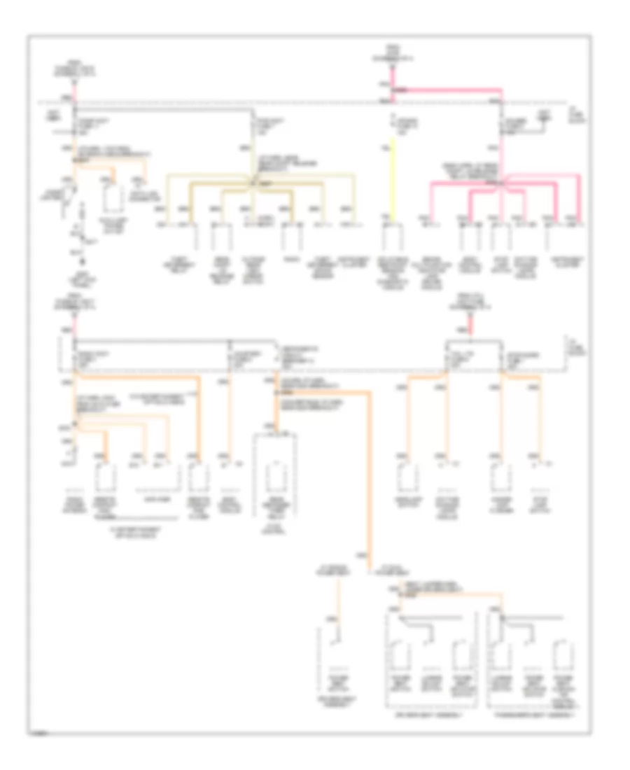
Power Distribution Wiring Diagram (2 of 4) for Chevrolet Camaro 1998
List of elements for Power Distribution Wiring Diagram (2 of 4) for Chevrolet Camaro 1998:
- (eng harn, near pcm breakout) s107
- (forward lamp harn, 15cm from underhood electrical center 1 breakout) s182
- (forward lamp harn, 20cm from underhood electrical center 1 breakout) s181
- (i/p harn, 2cm from radio connector breakout) s248
- (i/p harn, 4cm from data link connector breakout) s207
- (not used)
- A/c compressor relay
- A/c cruise mini fuse 15a
- A/t
- Abs ign mini fuse 10a
- Acc
- Automatic transmission
- Backup lamp switch (m/t)
- Body control module
- Bulb test
- Clutch pedal positon switch
- Cruise control clutch switch
- Cruise control module
- Cruise control release switch (brake)
- Cruise control switches
- Daytime running lamps module
- Electronic brake control module
- Electronic ignition control module (vin k)
- Electronic traction control module
- Electronic traction control switch (vin g)
- Eng ctrl mini fuse 15a
- Evaporative emission canister purge solenoid
- Evaporative emission canister vent solenoid
- From ign maxifuse (diagram 1 of 4)
- G109 (top right of radiator)
- Hvac control
- Hvac control selector switch
- Hvac fuse 6 20a
- I/p fuse block
- Ignition relay
- Ignition switch
- Lock
- M/t
- Multifuction lever
- Off
- Park/ neutral position switch
- Park/ neutral position switch (a/t)
- Pcm ign mini fuse 15a
- Pnk
- Powertrain control module
- Rear defogger switch
- Rear defogger time/ relay
- Red
- Run
- S112
- S164
- S165 (forward lamp harn, near underhood electrical center 2 breakout)
- S183
- S185
- Second gear start switch (vin k)
- Start
- Strtr mini fuse 15a
- To air bag fuse (diagram 3 of 4)
- To eng sen mini fuse (diagram 4 of 4)
- To wipe/ wash fuse (diagram 4 of 4)
- Turn b/u fuse 2 20a
- Turn signal lamp flasher
- Underhood electrical center 2
Power Distribution Wiring Diagram (3 of 4) for Chevrolet Camaro 1998
List of elements for Power Distribution Wiring Diagram (3 of 4) for Chevrolet Camaro 1998:
- (chev)
- (convertible) i/p harn, near g200 breakout)
- (dash harn, at rear compt lid release relay breakout) s206
- (i/p harn, 23cm from cd player breakout)
- (i/p harn, near rear compt release breakout)
- (not used)
- (pont)
- (seat jumper harn, under driver's seat) s320
- A13
- Air bag fuse 10 15a
- Amplifier
- Auxilliary power outlet
- Body control module
- Brake multifunction indicator lamp driver module
- Cigar accy fuse 11 25a
- Cigar lighter
- Courtesy fuse 6 20a
- Data link connector
- Daytime running lamps module
- Defog/seats circuit breaker 12 30a
- Driver's seat assembly
- E11
- E12
- From fusible link e (diagram 1 of 4)
- From fusible link f (diagram 1 of 4)
- From i/p 2 maxi fuse (diagram 1 of 4)
- From s185 (diagram 2 of 4)
- G200 (left kick panel)
- Gauges fuse 9 10a
- Hazard lamp flasher
- Headlamp switch
- Hvac control
- I/p fuse block
- Inflatable restraint sensing and diagnostic module
- Instrument cluster
- Lumbar adjust switch
- Nca
- Outside rear view mirror switch
- Passenger's seat assembly
- Pnk
- Power seat cushion air control module
- Power seat inflator switch
- Power seat switch
- Pwr accy fuse 7 15a
- Radio
- Radio accy fuse 4 25a
- Radio power antenna
- Rear compt lid release relay
- Rear defogger timer/ relay
- Red
- Remote compact disc player
- S207
- S217
- S255
- S333
- Stop lamp switch
- Stop/hzard fuse 1 20a
- Tail lts fuse 5 20a
- Theft deterrent relay
- Theft deterrent shock sensor
- W/ dual power seat
- W/ entertainment option d and e
- W/ single power seat
- W/o entertainment option d anb e
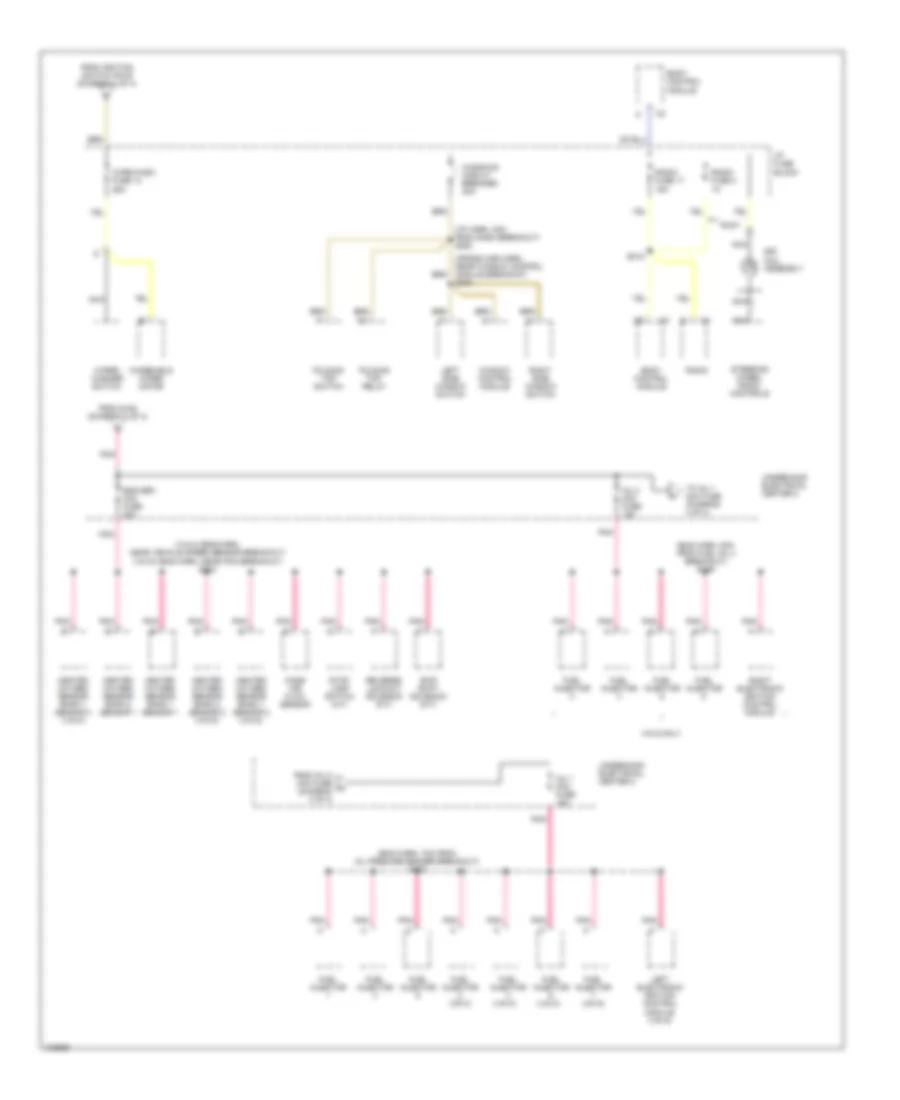
Power Distribution Wiring Diagram (4 of 4) for Chevrolet Camaro 1998
List of elements for Power Distribution Wiring Diagram (4 of 4) for Chevrolet Camaro 1998:
- (cross car harn, near window control module breakout) s208
- (eng harn, 7cm from oil presure sender breakout) s102
- (eng harn, 8cm from fuel inj 4 breakout) s109
- (i/p harn, 4cm from dash breakout) s253
- (vin k)
- (vin k) (eng harn, near vehicle speed sensor breakout) (vin g) (eng harn, near pcm breakout) s104
- Body control module
- Eng sen mini fuse 20a
- Folding top relay
- Folding top switch
- From ignition switch pin e (diagram 2 of 4)
- From inj 2 mini fuse h (diagram 4 of 4)
- From s164 (diagram 2 of 4)
- Fuel injector
- Fuel injector (vin g)
- Fuel injector (vin k)
- Heated oxygen sensor bank 1 sensor 1
- Heated oxygen sensor bank 1 sensor 2 (vin g)
- Heated oxygen sensor bank 1 sensor 3 (vin k)
- Heated oxygen sensor bank 2 sensor 1
- Heated oxygen sensor bank 2 sensor 2 (vin g)
- I/p fuse block
- Inj 1 mini fuse 15a
- Inj 2 mini fuse 15a
- Left electronic ignition control module (vin g)
- Left side window switch
- Mass air flow sensor
- Nca
- Pnk
- Pont
- Radio
- Radio fuse 17 15a
- Radio fuse 3 1a
- Reverse lockout solenoid (m/t)
- Right electronic ignition control module
- Right side window switch
- S218
- Sir coil assembly
- Skip shift solenoid (m/t)
- Steering wheel radio controls
- Stop lamp switch (a/t)
- To inj 1 mini fuse (diagram 4 of 4)
- Underhood electrical center 2
- Vin g only
- Window control module
- Windows circuit breaker 30a
- Windshield wiper motor
- Wipe/wash fuse 14 25a
- Wiper/ washer switch