POWER DISTRIBUTION
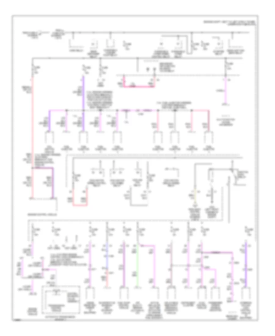
Power Distribution Wiring Diagram (1 of 4) for Chevrolet Cruze LT 2013

List of elements for Power Distribution Wiring Diagram (1 of 4) for Chevrolet Cruze LT 2013:
- (1.4l)
- (1.4l: fuel injector harness, 9 cm from throttle body breakout) (1.8l: engine harness, 18.5 cm from breakout for intake camshaft position actuator)
- (1.8l)
- (engine compt, next to left strut tower) underhood fuse block
- (forward lamp harness, 5 cm from main bundle in breakout for underhood fuse block) j116
- (not used)
- A/c compressor clutch relay
- Audio amplifier (w/ amplifier)
- Automatic transmission assembly (a/t)
- B x1
- Battery
- Battery fuse block (engine compt, next to left strut tower)
- Body control module
- Brake booster pump motor relay
- Control solenoid valve assembly
- Cooling fan high speed relay
- Driver window motor
- Driver window switch
- Driver window switch (if equipped)
- Electronic brake control module
- Engine control module
- Engine controls ignition relay
- Engine coolant thermostat heater
- Evaporative emission purge solenoid valve
- Front fog lamp relay
- Fuel pump control module
- Fuse 10a
- Fuse 15a
- Fuse 20a
- Fuse 250a
- Fuse 25a
- Fuse 30a
- Fuse 40a
- Fuse 5a
- Fuse 60a
- Fuse 7.5a
- Fuse 80a
- Generator
- Heated oxygen sensor 1
- Heated oxygen sensor 2
- Intake manifold tuning solenoid valve (1.8l)
- J111
- J129
- J301 (body harness, 8 cm from x225 breakout)
- Keyless entry control module (w/ remote entry lock control)
- Left front fog lamp
- Left rear window switch
- Nca
- Outside rearview mirror switch
- Passenger presence detection module
- Passenger window switch
- Power steering control module
- Red
- Right front fog lamp
- Right rear window switch
- Seat heating control module
- Secondary air injection pump relay
- Starter motor
- Sunroof control module (if equipped)
- To fuse 1 (diagram 3 of 4)
- To fuse 9 (diagram 2 of 4)
- To horn relay (diagram 2 of 4)
- Transmission control module
- Turbocharger bypass solenoid valve (1.4l)
- Turbocharger wastegate solenoid valve (1.4l)
- W/ express up/down window
- W/ front seat heater
- W/o express up/down window
- X211
- X310
- X320
- X500
- X600
- X700
- X800
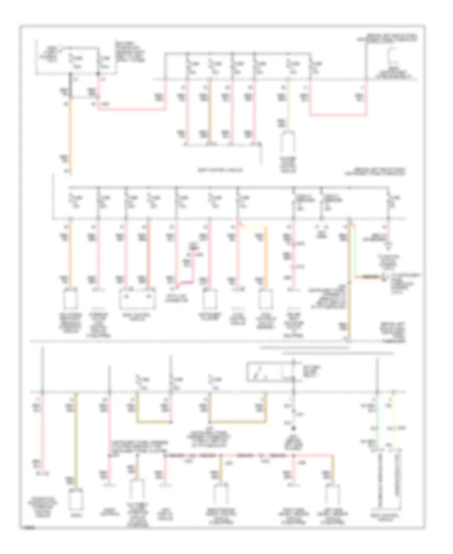
Power Distribution Wiring Diagram (2 of 4) for Chevrolet Cruze LT 2013
List of elements for Power Distribution Wiring Diagram (2 of 4) for Chevrolet Cruze LT 2013:
- (1.4l: 8 cm from engine control module breakout) (1.8l: 22.5 cm from breakout for intake camshaft position actuator)
- (1.4l: engine harness, 30 cm from breakout for engine control module) j112
- (1.8l: engine harness, 24 cm from breakout for intake camshaft position actuator) (1.4l: engine harness, 9 cm from throttle body breakout) j114
- (1.8l: fuel injector harness, 5 cm from breakout for fuel injector 4) j108
- (engine compt, next to left strut tower) underhood fuse block
- (not used)
- 1.4l
- 1.8l
- 1.8l (ving)
- A/t
- Active grille air shutter actuator (w/ engine improvement fuel economy)
- Air quality sensor (automatic a/c)
- Automatic transmission assembly
- Coil ignition module
- Control solenoid valve assembly
- Cooling fan low speed relay
- Cooling fan medium speed relay
- Cooling fan relay
- Cooling fan speed control relay
- Engine control module
- Evaporative emission vent solenoid valve
- From body control module (diagram 4 of 4)
- From fuse 24 c (diagram 1 of 4)
- From fuse 47 b (diagram 1 of 4)
- Fuel injector
- Fuel pump control module
- Fuse 10a
- Fuse 15a
- Fuse 30a
- Fuse 5a
- Fuse 60a
- Fuse 7.5a
- G101 (left front corner of engine compt)
- Headlamp high beam relay
- Horn relay
- Hvac control module
- Ignition main relay
- Inflatable restraint sensing & diagnostic module
- Inside rearview mirror (if equipped)
- Instrument cluster
- J144
- J309
- M/t
- Multi-function intake air sensor
- Passenger air bag disable indicator
- Rear defogger relay
- Rearview camera
- Secondary air injection solenoid valve relay
- Starter relay
- Steering column lock control module (if equipped)
- Transmission control module
- Windshield washer pump relay
- Windshield wiper relay
- Windshield wiper speed control relay
- X160
- X190
- X200
- X211
- X3 (not used)
- X401 m
- X900
- X915
Power Distribution Wiring Diagram (3 of 4) for Chevrolet Cruze LT 2013
List of elements for Power Distribution Wiring Diagram (3 of 4) for Chevrolet Cruze LT 2013:
- (behind left end of dash) instrument panel fuse block
- (instrument panel harness, 10 cm from breakout for instrument panel cluster) j203
- (not used)
- Battery fuse block (engine compt, next to left strut tower)
- Battery saver relay 1
- Blower motor control module
- Body control module
- Circuit breaker 25a
- Data link connector
- Driver seat adjuster switch (if equipped)
- From a fuse 5 (diagram 1 of 4)
- Fuse 100a
- Fuse 10a
- Fuse 15a
- Fuse 20a
- Fuse 25a
- Fuse 2a
- Fuse 30a
- Fuse 40a
- Fuse 7.5a
- G201 (behind left side of dash)
- Hvac control module
- Hvac controls switch assembly
- Inflatable restraint sensing & diagnostic module
- Info display module
- Instrument cluster
- J201
- J206 (instrument panel harness, in breakout to relay section of i/p fuse block)
- J207 (instrument panel harness, in breakout to relay section of i/p fuse block)
- J320
- J495
- Left side object sensor module (if equipped)
- Logistics relay ctrl
- Multimedia player interface module (w/ audio interface)
- Radio
- Radio controls
- Rear compartment lid release relay
- Rear parking assist control module (if equipped)
- Red
- Right side object sensor module (if equipped)
- Steering column lock control module (if equipped)
- Technology identification
- Telematics communication interface control module
- To ignition switch (diagram 4 of 4)
- To instrument panel fuse block (diagram 4 of 4)
- X200
- X310
- X402
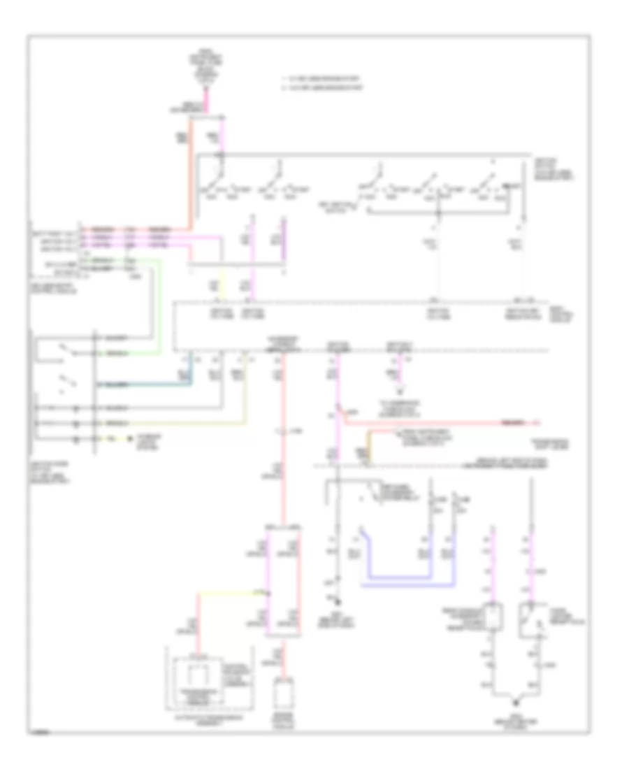
Power Distribution Wiring Diagram (4 of 4) for Chevrolet Cruze LT 2013
List of elements for Power Distribution Wiring Diagram (4 of 4) for Chevrolet Cruze LT 2013:
- (behind left end of dash) instrument panel fuse block
- A/t
- Acc
- Accessory wakeup serial data
- Automatic transmission assembly
- Batt post volt
- Body control module
- Cigar lighter receptacle
- Control solenoid valve assembly
- Engine control module
- From instrument panel fuse block (diagram 3 of 4)
- Fuse 20a
- G201 (behind left side of dash)
- G203 (behind center of dash)
- Ignition 3 rly ctrl
- Ignition key resistor sig
- Ignition mode switch (w/ keyless engine start)
- Ignition switch (w/o keyless engine start)
- Ignition volt
- Ignition voltage
- Interior lights system
- J119
- J201
- Key ignition switch
- Keyless entry control module
- M/t
- Off
- Rear console accessory power receptacle
- Retained accessory power relay
- Run
- Start
- Sw 2 lo ref
- Sw sig 2
- To underhood fuse block (diagram 2 of 4)
- Transmission control module
- Transmission shift lever
- W/ keyless engine start
- W/o keyless engine start
- X190
- X200
- X300