POWER DISTRIBUTION
Power Distribution Wiring Diagram for Mercedes-Benz C320 2003
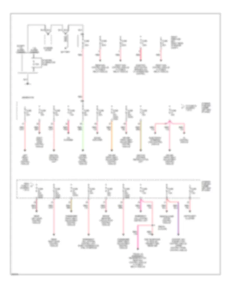
List of elements for Power Distribution Wiring Diagram for Mercedes-Benz C320 2003:
- (diagram 1 of 2)
- 1.8l super- charged
- 175a
- Battery
- Brake booster vacuum pump control module
- Cd changer
- Central gateway control unit
- Comfort acc pushbutton control module, upper control panel control module
- D2b telephone & tele aid transmitter/ receiver
- Di control module
- Driver front seat adjustment control module
- Electric suction fan engine & a/c w/ integrated control
- Electronic steering lock control module
- Emergency call system control unit
- Emergency call system control unit, e-net compensator, ctel interface
- Except 1.8l super- charged
- From fuse 31 a
- Front pre-fuse box (right rear of engine compt)
- Front sam control module w/ fuse & relay module
- Fuse 125a
- Fuse 15a
- Fuse 200a
- Fuse 20a
- Fuse 25a ('03)
- Fuse 30a
- Fuse 30a (c230)
- Fuse 30a (c240, c320)
- Fuse 60a
- Fuse 7.5a
- Generator
- Heating systems recirculation unit
- Instrument cluster
- Interior fuse box (under left end of dash)
- Left front door control module
- Passenger front seat adjustment control module
- Rear blower motor control module
- Rear left door control module
- Rear right door control module
- Rear sam control module w/ fuse & relay module
- Red
- Red/ pnk
- Right front door control module
- Sedan & coupe
- Sound amplifier
- Starter motor
- Starter/ alternator fuse
- To fuse 32 (diagram 1 of 2)
- Trunk lid emergency release switch, rear sam control module w/ fuse & relay module
- Upper control panel control module
 English