POWER DISTRIBUTION
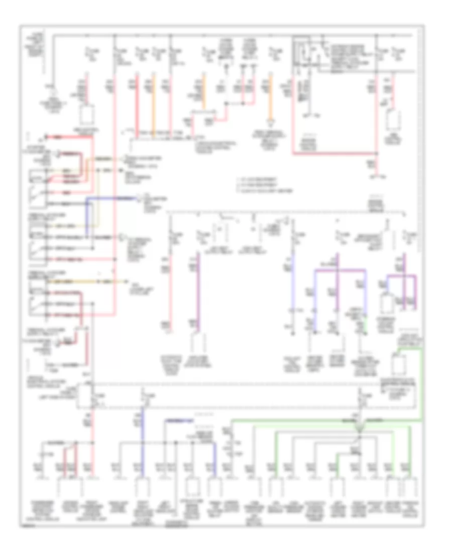
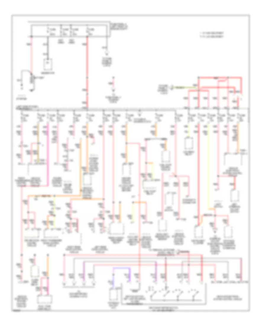
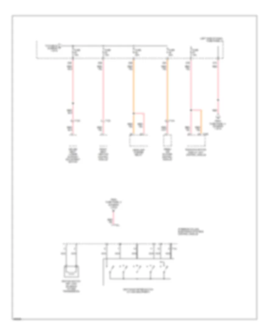
Power Distribution Wiring Diagram, Early Production (1 of 5) for Volkswagen Jetta S 2011

List of elements for Power Distribution Wiring Diagram, Early Production (1 of 5) for Volkswagen Jetta S 2011:
- (left side of dash) fuse panel c
- (not used)
- 20b
- 22b
- 24a
- 24b
- 35a
- 35b
- 36a
- 36b
- 39a
- 39b
- 43b
- 46b
- 48b
- 51b
- 55a
- 55b
- 57a
- 57b
- A/t
- Access/start authorization control module
- Air bag spiral spring/ return spring w/ slip ring
- Alarm horn relay
- Battery
- Converter box
- Data bus on board diagnostic interface
- Dual tone horn relay
- Front passenger door control module
- Fuse
- Fuse 10a
- Fuse 15a
- Fuse 1a (or 10a)
- Fuse 200a
- Fuse 20a
- Fuse 25a
- Fuse 30a
- Fuse 80a
- Fuse panel a (left front of engine compt)
- G605 (on steering column)
- Generator
- Headlamp dimmer/ flasher switch
- Heater control module
- Ignition switch key lock solenoid
- Ignition/starter switch (w/ low equipment)
- Instrument cluster
- Interior monitoring sensor
- Left rear door control module
- Light switch
- Low beam relay
- Nca
- Power sunroof control module
- Radio/navigation display unit control module
- Red
- Right rear door control module
- Starter
- Steering angle sensor (if equipped)
- T10s
- T16d
- T28a
- T28b
- T28c
- T52c
- T73a
- T73b
- Tiptronic switch
- To climatronic control module (diagram 5 of 5)
- To fuse 47 (diagram 5 of 5)
- To fuse panel b (diagram 2 of 5)
- To fuse panel c (diagram 3 of 5)
- To steering column electronics control module (diagram 5 of 5)
- Vehicle electrical control module
- Vehicle electrical system control module
- W/ auxiliary coolant heater
- W/ high equipment
- W/ low equipment
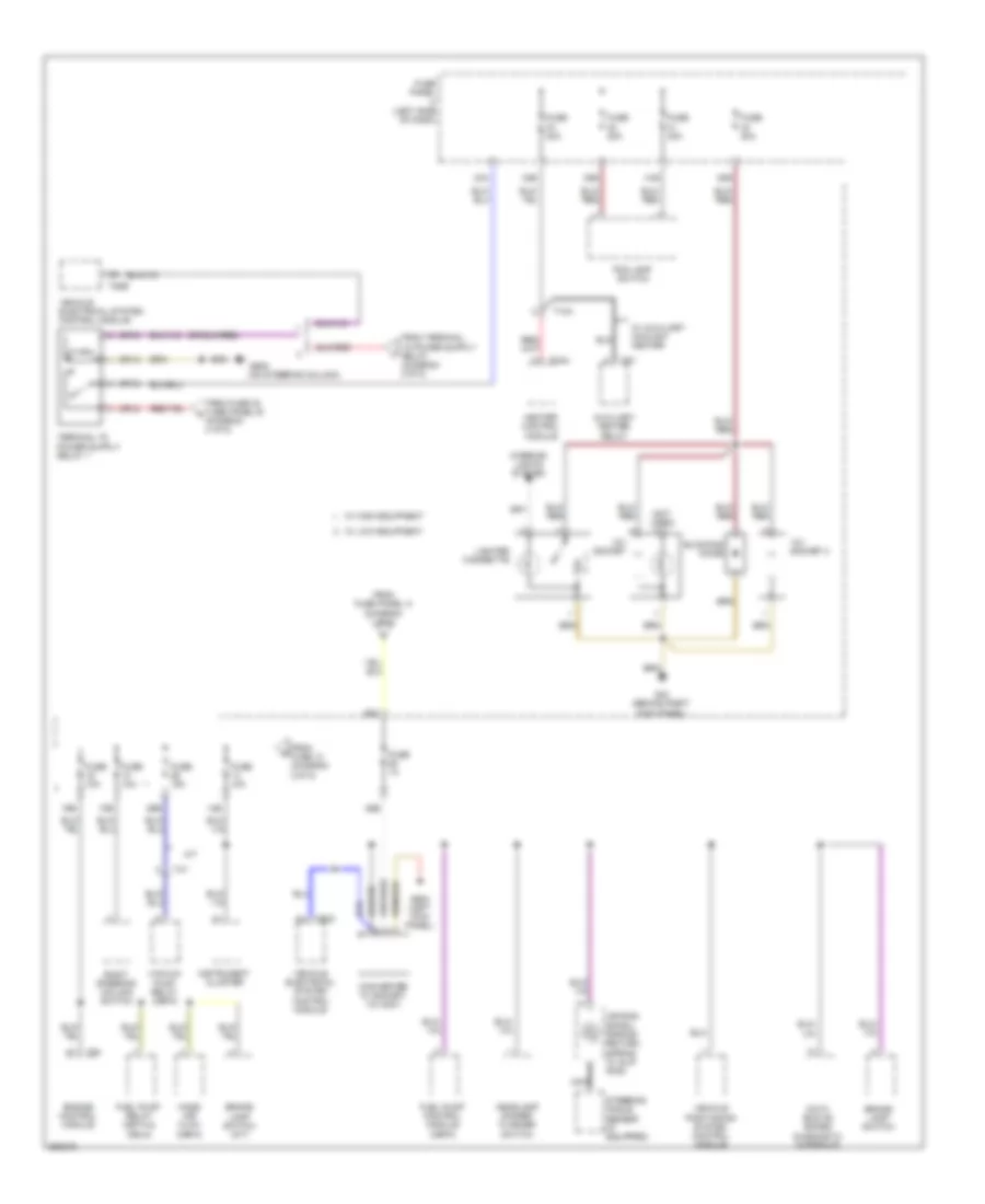
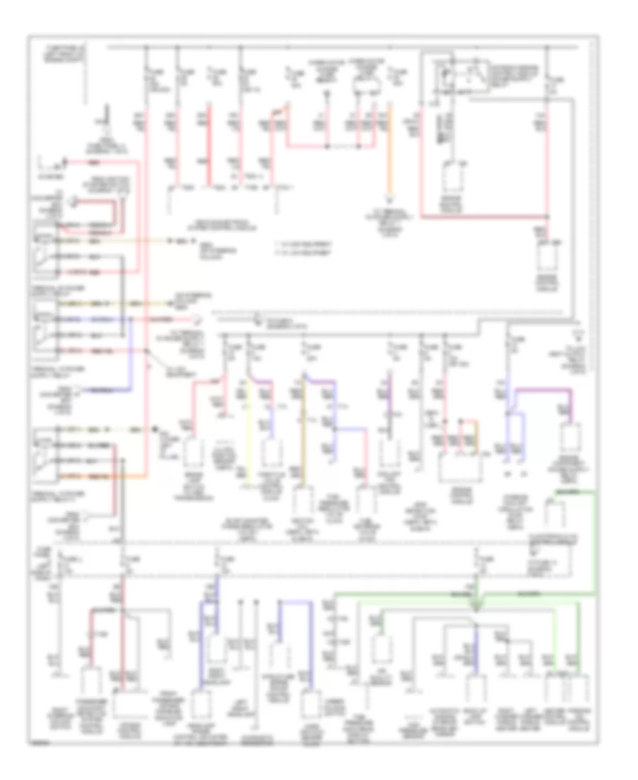
Power Distribution Wiring Diagram, Early Production (2 of 5) for Volkswagen Jetta S 2011
List of elements for Power Distribution Wiring Diagram, Early Production (2 of 5) for Volkswagen Jetta S 2011:
- (cbfa)
- (except
- (lower left "a" pillar)
- (not used)
- (or 5)
- (or 61)
- (or 62)
- 13b
- 14a
- 15b
- 16a
- 19a
- 20a
- 23a
- 25a
- 26a
- 28a
- 29a
- 30a
- 31a
- Abs control module
- Air bag control module
- Air quality sensor
- Amplifier (w/0 start/ stop system)
- Automatic dimming interior rearview mirror
- Automatic glow time control module (cjaa)
- Backup lamp switch
- Cbfa)
- Cjaa w/ auxiliary heater
- Climatronic & a/c control module
- Coolant circulation pump relay
- Coolant fan control module
- Diagnostic connector
- Engine control module
- Fresh air blower relay
- From converter box (diagram 1 0f 5)
- From fuse panel a (diagram 1 of 5)
- Front passenger air bag disabled indicator lamp
- Fuse 15a
- Fuse 30a
- Fuse 40a
- Fuse 40a (or 20a)
- Fuse 50a
- Fuse 5a
- Fuse 5a (or 1a)
- Fuse 60a
- Fuse panel b (left front of engine compt)
- Fuse panel c (left side of dash)
- G44
- G605 (on steering column)
- Headlamp range control
- Heated oxygen sensor
- Heated oxygen sensor 2 (cbfa)
- Heater control module
- High heat output relay
- High pressure sensor
- Left front headlamp
- Left washer nozzle heater
- Low heat output relay
- Mass air flow sensor (cjaa)
- Mirror folding switch
- Nca
- Oxygen sensor after three way catalytic converter
- Parking aid control module
- Passenger occupant detection system control module
- Red
- Right front headlamp adjuster (w/ high equipment)
- Right washer nozzle heater
- Secondary air injection pump relay
- Starter
- Steering column control module
- Structure borne sound control module
- T10b
- T28
- T32f
- T4x
- T52a
- T52b
- T52c
- T73a
- T73b
- T94
- Tire pressure monitor- ing display button
- To converter box (diagram 1 of 5)
- To converter box (diagram 4 of 5)
- To fuse 14 (diagram 3 0f 5)
- To fuse 6 (diagram 4 0f 5)
- Vehicle electrical system control module
- W/ esp
- W/ high equipment
- W/ low equipment
- Wiper motor change over- relay 1
- Wiper motor change over- relay 2
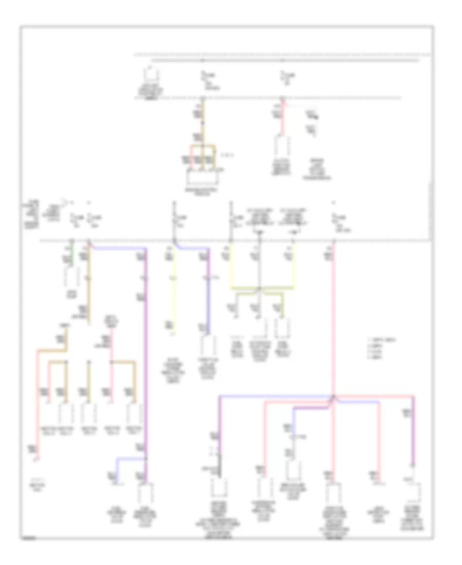
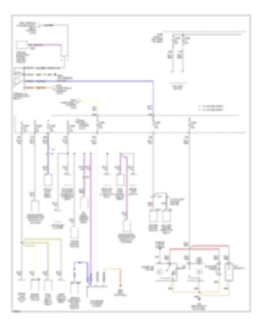
Power Distribution Wiring Diagram, Early Production (3 of 5) for Volkswagen Jetta S 2011
List of elements for Power Distribution Wiring Diagram, Early Production (3 of 5) for Volkswagen Jetta S 2011:
- (not used)
- (on steering column)
- (or 2)
- (or 4)
- (or 6)
- (or 8)
- 10b
- 12v socket
- 12v socket 2
- 14b
- 16b
- 26b
- 30b
- 31b
- 32b
- 33a
- 33b
- 58a
- 58b
- A/t
- Air bag spiral spring/ return spring w/ slip ring
- Auxiliary heater relay
- Blocking diode
- Brake lamp switch
- Brake lamp switch (m/t)
- Converter w/ socket, 12v-230v
- Data bus on board diagnostic interface
- Engine control module
- Fog lamp switch
- From fuse 13 (diagram 2 0f 5)
- From fuse 30 fuse panel b (diagram 2 0f 5)
- From fuse panel a (diagram 1 0f 5)
- Fuel pump control module (cbfa)
- Fuel pump relay (cbta & cbua)
- Fuse 10a
- Fuse 15a
- Fuse 1a
- Fuse 20a
- Fuse 30a
- Fuse 40a
- Fuse panel c (left side of dash)
- G43 (behind right kick panel)
- G602 (left kick panel)
- G605
- Headlamp dimmer/ flasher switch
- Heater control module
- Instrument cluster
- Interior lights system
- Lighter cigarette
- Mass air flow (cbfa)
- Nca
- Right steering column switch
- Steering angle sensor (if equipped)
- T10a
- T4y
- T52b
- T52c
- T5aa
- T94
- T9y
- Vacuum pump relay (cbfa)
- Vehicle electrical system control module
- Vehicle positioning system control module
- W/ auxiliary coolant heater
- W/ high equipment
- W/ low equipment
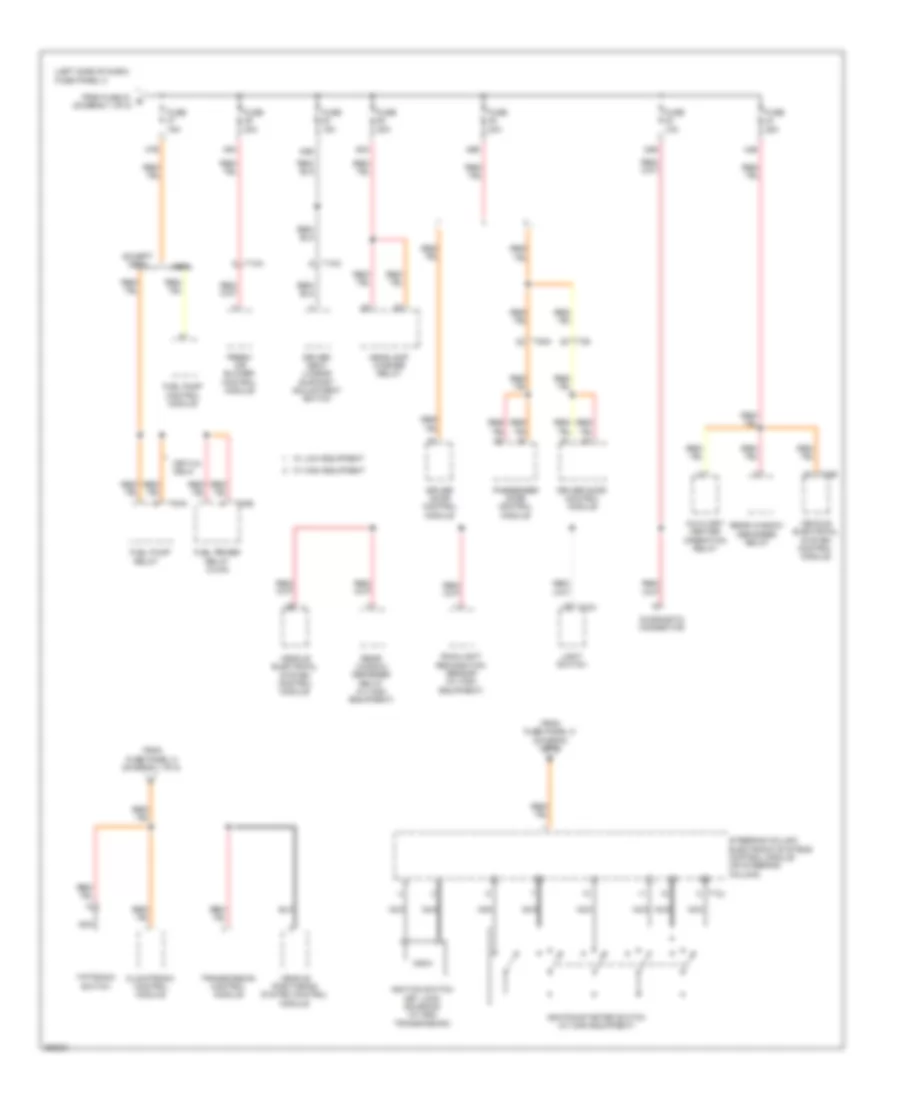
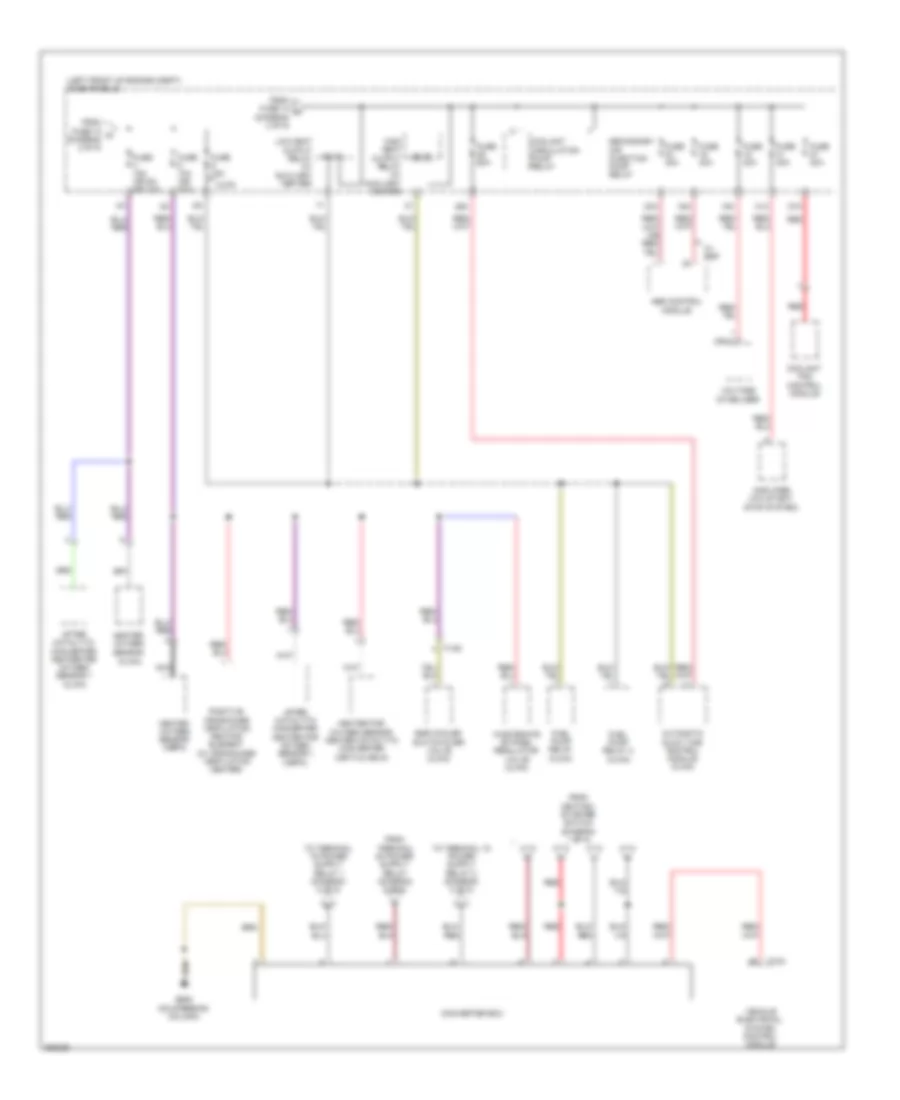
Power Distribution Wiring Diagram, Early Production (4 of 5) for Volkswagen Jetta S 2011
List of elements for Power Distribution Wiring Diagram, Early Production (4 of 5) for Volkswagen Jetta S 2011:
- (or red)
- (w/ auxiliary heater) high heat output relay
- (w/ auxiliary heater) low heat output relay
- 10a
- Automatic glow time control module (cjaa)
- Brake lamp switch (w/ dsg transmission)
- Cbfa
- Cbpa
- Cbta, cbua
- Cbta, cbua & cbfa
- Cjaa
- Clutch position sensor (cbpa m/t)
- Coolant circulation pump relay (cbfa)
- Egr cooler switch-over valve (cjaa)
- Engine control module
- Evap canister purge regulator valve 1 (cbpa)
- Fuel metering valve (cjaa)
- Fuel pressure regulator valve (cjaa)
- Fuel pump relay (cjaa)
- Fuel pump relay 2 (cjaa)
- Fuse 10a
- Fuse 10a (or 15a)
- Fuse 15a (or 25a)
- Fuse 20a
- Fuse 5a
- Fuse panel b (left front of engine compt)
- Heated oxygen sensor (cbpa) oxygen sensor in bank 1 center three way catalytic converter (cbta & cbua)
- Ignition coil
- Ignition coil 1
- Ignition coil 2
- Ignition coil 3
- Ignition coil 4
- Ignition coil 5
- L from fuse 3 (diagram 2 of 5)
- Leak detection pump (cbfa)
- Leak pump
- Oxygen sensor after three way catalytic converter
- Positive crankcase ventilation heating element (w/ crankcase ventilation heater)
- T10g
- T14
- T94
- Throttle valve control module (cjaa)
- Wastegate bypass regulator valve (cjaa)
Power Distribution Wiring Diagram, Early Production (5 of 5) for Volkswagen Jetta S 2011
List of elements for Power Distribution Wiring Diagram, Early Production (5 of 5) for Volkswagen Jetta S 2011:
- (left side of dash) fuse panel c
- 23b
- 44b
- 45b
- 47b
- 49a
- 52a
- 53b
- Auxiliary heater operation relay
- Cbfa
- Cbta & cbua
- Climatronic control module
- Diagnostic connector
- Driver door control module
- Driver seat lumbar support adjustment switch
- Except cbfa
- Fresh air blower control module
- From fuse 51 b (diagram 1 of 5)
- From fuse panel c (diagram 1 0f 5)
- From fuse panel c (diagram 1 of 5)
- Fuel primer relay (cjaa)
- Fuel pump
- Fuel pump control module
- Fuse 10a
- Fuse 15a
- Fuse 20a
- Fuse 25a
- Fuse 30a
- Headlamp washer relay
- Ignition switch key lock solenoid (w/ dsg transmission)
- Ignition/starter switch (w/ high equipment)
- Light switch
- Nca
- Passenger door control module
- Rain/light recognition sensor (w/ high equipment)
- Rear window defogger relay
- Rear window defogger relay (w/ high equipment)
- Relay
- Steering column electronic systems control module (on steering column)
- T10a
- T10c
- T10h
- T12j
- T28
- T28a
- T5aa
- T5ab
- T73b
- Tiptronic switch
- Transmission control module
- Vehicle electrical system control module
- Vehicle positioning system control module
- W/ high equipment
- W/ low equipment
Power Distribution Wiring Diagram, Late Production (1 of 5) for Volkswagen Jetta S 2011
List of elements for Power Distribution Wiring Diagram, Late Production (1 of 5) for Volkswagen Jetta S 2011:
- (left side of dash) fuse panel c
- (not used)
- 20b
- 22b
- 23b
- 24a
- 24b
- 35a
- 35b
- 36a
- 36b
- 39a
- 39b
- 43b
- 44b
- 45b
- 46b
- 47b
- 48b
- 51b
- 55a
- 55b
- A/t
- Access/ start authori- zation control module
- Alarm horn relay
- Auxiliary heater operation relay
- Battery
- Cbfa
- Cbpa
- Data bus on board diagnostic interface
- Diagnostic connector
- Driver door control module
- Dual tone horn relay
- Front passenger control module
- Front passenger door control module
- Fuel pump control module
- Fuel pump relay
- Fuse 10a
- Fuse 15a
- Fuse 200a
- Fuse 20a
- Fuse 25a
- Fuse 30a
- Fuse 7.5a
- Fuse 80a
- Fuse panel a (left front of engine compt)
- Generator
- Heater control module (w/ auxiliary coolant heater)
- Ignition switch key lock solenoid (w/ dsg transmission)
- Ignition/starter switch (w/ low equipment)
- Instrument cluster
- Left rear door control module
- Left steering column switch
- Light switch
- Low beam relay
- Nca
- Power sunroof control module
- Rain/light recognition sensor
- Rear window defogger relay
- Red
- Right rear door control module
- Starter
- T10h
- T10s
- T20a
- T20b
- T20c
- T28
- T28a
- T28b
- T28c
- T32f
- T52b
- T52c
- T5aa
- T73a
- T73b
- Tiptronic switch (a/t)
- To converter box (diagram 4 of 5)
- To fuse 53 (diagram 5 of 5)
- To fuse panel b (diagram 2 of 5)
- To fuse panel c (diagram 3 of 5)
- To fuse panel c (diagram 5 of 5)
- To steering column electronics control module (diagram 5 of 5)
- Vehicle electrical control module
- Vehicle electrical system control module
- W/ high equipment
- W/ low equipment
Power Distribution Wiring Diagram, Late Production (2 of 5) for Volkswagen Jetta S 2011
List of elements for Power Distribution Wiring Diagram, Late Production (2 of 5) for Volkswagen Jetta S 2011:
- (not used)
- (on steering column) g605
- (or 1)
- (or 2)
- (or 3)
- (or 5)
- (or 61)
- (or 62)
- 1 (or 4)
- 10a
- 10b
- 13a
- 13b
- 14a
- 15b
- 19a
- 2 (or 6)
- 20a
- 25a
- 28a
- 29a
- 3 (or 2)
- 30a
- 5 (or 8) red
- Air bag control module
- Air quality sensor
- Automatic dimming interior rearview mirror
- Back up lamp switch
- Brake lamp switch (w/ dsg transmission)
- Cbfa & cjaa
- Climatronic & a/c control module
- Clutch position sensor (cbpa)
- Coolant fan control module
- Diagnostic connector
- Engine control module
- Evap canister purge regulator valve 1 (cbpa)
- From converter box (diagram 4 of 5)
- From fuse panel a (diagram 1 of 5)
- From ignition/ starter switch (diagram 1 of 5)
- Front passenger air bag disabled indicator lamp
- Fuel metering valve (cjaa)
- Fuel pressure regulator valve (cjaa)
- Fuse 10a
- Fuse 10a (or 15a)
- Fuse 20a
- Fuse 30a
- Fuse 40a (or 20a)
- Fuse 50a
- Fuse 5a
- Fuse 5a (or 1a)
- Fuse panel b (left front of engine compt)
- Fuse panel c (left side of dash)
- G44 (lower left "a" pillar)
- G605 (on steering column)
- Headlamp range control adjuster (w/ high equipment)
- Heater control module
- High pressure sensor
- Ignition coil (cbpa, cbta & cbua)
- Interior coolant circulation pump relay (cbfa)
- Leak detection pump (cbpa, cbta & cbua)
- Left front headlamp
- Left washer nozzle heater
- Mass air flow sensor (cjaa)
- Mirror folding switch
- Nca
- Parking aid control module
- Passenger occupant detection system control module
- Red
- Right front headlamp
- Right steering column switch
- Right washer nozzle heater
- Starter
- Structure borne sound control module
- T10b
- T14
- T20c
- T28
- T32f
- T4x
- T52a
- T52c
- T73a
- T73b
- T94
- Throttle valve control module (cjaa)
- Tire pressure monitoring display button
- To converter box (diagram 4 of 5)
- To fuse 14 (diagram 3 0f 5)
- To fuse 9 (diagram 4 0f 5)
- To low heat output relay (diagram 4 0f 5)
- Vehicle electrical system control module
- W/ high equipment
- W/ low equipment
- Wiper motor change over relay 1
- Wiper motor change over relay 2
Power Distribution Wiring Diagram, Late Production (3 of 5) for Volkswagen Jetta S 2011
List of elements for Power Distribution Wiring Diagram, Late Production (3 of 5) for Volkswagen Jetta S 2011:
- (not used)
- (or 2)
- (or 4)
- (or 6)
- (or 8)
- 12v socket
- 12v socket 2
- 14b
- 16b
- 26b
- 27b
- 30b
- 31b
- 32b
- 33a
- 33b
- 58a
- 58b
- A/t
- Air bag spiral spring/return
- Air bag spiral spring/return spring with slip ring
- Auxiliary heater operation relay
- Blocking diode
- Brake lamp switch
- Brake lamp switch (m/t)
- Cigarette lighter
- Converter w/ socket, 12v-230v
- Cruise control switch
- Data bus on board diagnostic interface (cbfa)
- Engine control module
- Fog lamp switch
- From c fuse panel a (diagram 1 of 5)
- From fuse 13 (diagram 2 0f 5)
- From fuse panel b (diagram 2 of 5)
- Fuel pump control module (cbfa)
- Fuel pump relay (cbta & cbua)
- Fuse 10a
- Fuse 15a
- Fuse 20a
- Fuse 30a
- Fuse 40a
- Fuse 5a
- Fuse panel c (left side of dash)
- G43 (behind right kick panel)
- G602 (left kick panel)
- G605 (on steering column)
- Headlamp switch illumination bulb
- Heater control module
- Instrument cluster
- Interior lights system
- Mass airflow sensor (cbfa)
- Oil level thermal sensor (cbfa)
- Spring with slip ring
- T10a
- T4y
- T52b
- T52c
- T5aa
- T6z
- T94
- Vacuum pump relay (cbpa)
- Vehicle electrical system control module
- W/ auxiliary coolant heater
- W/ high equipment
- W/ low equipment
Power Distribution Wiring Diagram, Late Production (4 of 5) for Volkswagen Jetta S 2011
List of elements for Power Distribution Wiring Diagram, Late Production (4 of 5) for Volkswagen Jetta S 2011:
- (cjaa)
- (left front of engine compt) fuse panel b
- (or 2)
- 15a
- 16a
- 23a
- 26a
- 27a
- 31a
- Abs control module
- After catalytic converter heater for oxygen sensor 1 (cbpa)
- After catalytic converter heater for oxygen sensor 1 (cjaa)
- Amplifier (w/0 start/ stop system)
- Automatic glow time control module (cjaa)
- Cjaa
- Converter box
- Coolant circulation pump relay
- Coolant fan control module
- Egr cooler switch-over valve (cjaa)
- From fuse 10 q (diagram 2 of 5)
- From fuse 14 r (diagram 2 of 5)
- From ignition/ starter switch (diagram 1 of 5)
- Fuel pump relay (cjaa)
- Fuel pump relay 2 (cjaa)
- Fuse 10a (or 20a)
- Fuse 15a
- Fuse 15a (or 5a, or 10a)
- Fuse 30a
- Fuse 40a
- Fuse 60a
- G605 (on steering column)
- Heated oxygen sensor (cbpa)
- Heater for oxygen sensor center catalytic converter (cbta & cbua)
- Heater oxygen sensor
- High heat output relay (w/ auxiliary heater)
- Low heat output relay (w/ auxiliary heater)
- Nca
- Positive crankcase ventilation heating element (w/ crankcase ventilation heater)
- Red
- Secondary air injection pump relay
- T10g
- T73a
- Vehicle electrical system control module
- Voltage stabilizer
- W/ esp
- Wastegate bypass regulator valve (cjaa)
Power Distribution Wiring Diagram, Late Production (5 of 5) for Volkswagen Jetta S 2011
List of elements for Power Distribution Wiring Diagram, Late Production (5 of 5) for Volkswagen Jetta S 2011:
- (left side of dash) fuse panel c
- 49a
- 50b
- 52b
- 53b
- 57a
- 57b
- Driver seat lumbar support adjustment switch
- Fresh air blower control module
- From fuse panel a (diagram 1 of 5)
- From fuse panel c (diagram 1 of 5)
- Front seat heating control module
- Fuse 15a
- Fuse 20a
- Headlamp washer relay
- Ignition switch key lock solenoid (w/ dsg transmission)
- Ignition/starter switch (w/ high equipment)
- Nca
- Radio/navigation display unit control module
- Red
- Steering column electronic systems control module
- T10a
- T10c
- T12j
- T16d
- T16l
- To fuse 20 d (diagram 1 of 5)