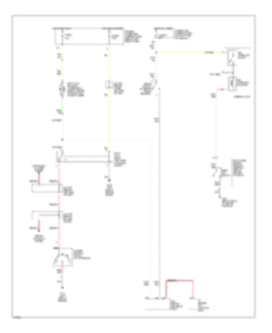
SHIFT INTERLOCK
Shift Interlock Wiring Diagram for Acura 3.2TL 2001
List of elements for Shift Interlock Wiring Diagram for Acura 3.2TL 2001:
- 7.5a
- A/t gear position switch (on transaxle)
- A28
- A32
- Brake switch (on brake pedal bracket)
- C27
- Driver's underdash fuse/relay box (behind left side of dash)
- Engine controls system
- Fuse 47 20a
- Fuse 8
- Fuse 9 7.5a
- G102 (left side of engine compt)
- G112 (left side of engine)
- G302 (below front of center console)
- Hot at all times
- Hot in acc or on
- Hot in on or start
- Instrument cluster system
- J/c c106 (behind blower motor)
- J/c c303 (behind left side of dash)
- J/c c452 (behind lower left side of dash)
- Key interlock solenoid
- Key interlock switch
- Not used
- O11
- Park pin switch
- Pcm (behind center of dash)
- Red
- Shift lever detent bracket assembly (below center console)
- Shift lock relay (left rear of engine compt)
- Shift lock solenoid (under right side of center console, next to shift lever)
- Steering lock
- Tp sensor (on throttle body)
- Underhood fuse/relay box (on right side of firewall)
 English