SHIFT INTERLOCK
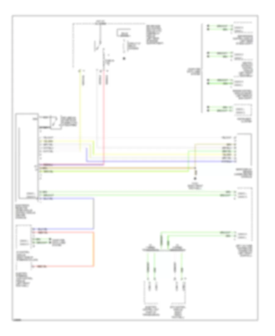
Shift Interlock Wiring Diagram for Mercedes-Benz E500 2005
List of elements for Shift Interlock Wiring Diagram for Mercedes-Benz E500 2005:
- Can-c h
- Can-c l
- Central gateway control module (left front footwell.)
- Circuit 87 relay, chassis
- Computer data lines system
- Di control module (right side of steering column)
- Driver side sam control module with fuse/relay module (left rear of engine compartment)
- Electric control unit (part of transmission)
- Electric steering lock control module (left front footwell)
- Electronic selector lever module control module (center console)
- Engine control module (me-sfi) (left rear of eng compt)
- Esp/sps/bas control module (left rear of eng compt)
- Etc control module (right front footwell)
- Fuse 45 7.5a
- Gear display sensor (under center console)
- Gnd
- Hot at all times
- Instrument cluster
- Keyless go start/stop pushbutton (if equipped)
- Left voltage distributor connector (left front door sill)
- Nca
- Solid state
- W/ 5 speed transmission
- W/ 7 speed transmission
- W15/1 (right front footwell)
 English