STARTING/CHARGING
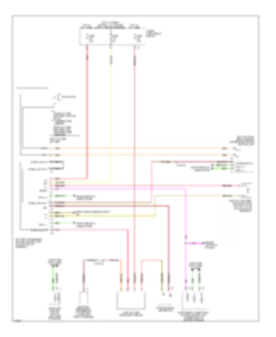
Battery Management System Wiring Diagram, Early Production for Mercedes-Benz E400 Hybrid 2014

List of elements for Battery Management System Wiring Diagram, Early Production for Mercedes-Benz E400 Hybrid 2014:
Battery Management System Wiring Diagram, Late Production for Mercedes-Benz E400 Hybrid 2014
List of elements for Battery Management System Wiring Diagram, Late Production for Mercedes-Benz E400 Hybrid 2014:
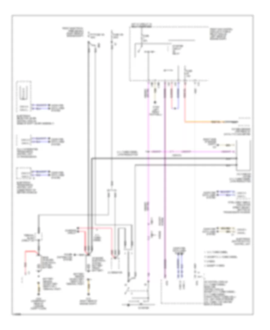
Starting Wiring Diagram for Mercedes-Benz E400 Hybrid 2014
List of elements for Starting Wiring Diagram for Mercedes-Benz E400 Hybrid 2014: