SUPPLEMENTAL RESTRAINTS
Supplemental Restraints Wiring Diagram for Chevrolet Tracker 2004
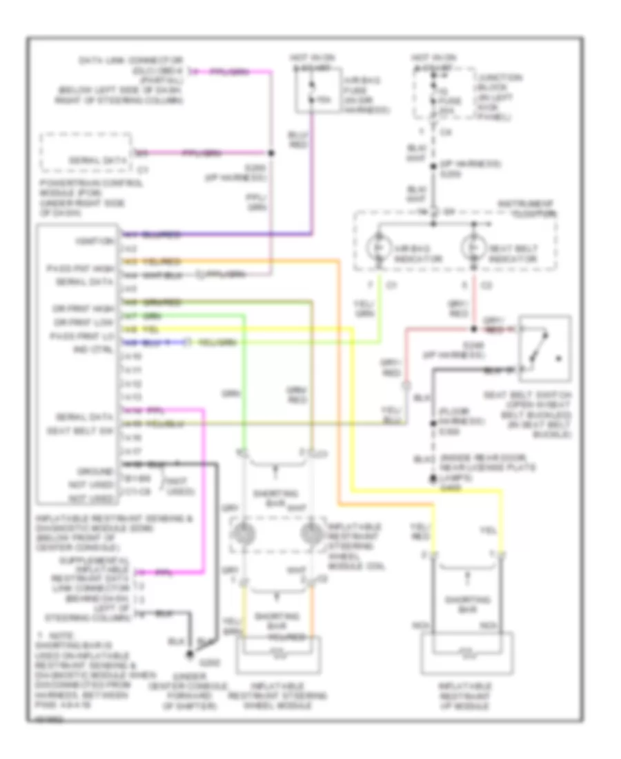
List of elements for Supplemental Restraints Wiring Diagram for Chevrolet Tracker 2004:
- (floor harness) s300
- (i/p harness) s250
- (not used)
- (under center console, forward of shifter)
- 15a
- A10
- A11
- A12
- A13
- A14
- A15
- A16
- A17
- A18
- Air bag fuse (in sir harness)
- Air bag indicator
- B1-b8
- C1-c8
- Data link connector (dlc) obd-ii (partial) (below left side of dash, right of steering column)
- Dr frnt high
- Dr frnt low
- G202
- Ground
- Hot in on & start
- Ig fuse 20a
- Ignition
- Ind ctrl
- Inflatable restraint i/p module
- Inflatable restraint sensing & diagnostic module (sdm) (below front of center console)
- Inflatable restraint steering wheel module
- Inflatable restraint steering wheel module coil
- Instrument cluster
- Junction block (in left kick panel)
- Left of steering column)
- Nca
- Near license plate lamps) g400
- Not used
- Note:
- Pass fnt high
- Pass frnt lo
- Powertrain control module (pcm) (under right side of dash)
- Restraint data link connector (behind dash,
- S249 (i/p harness)
- S260 (i/p harness)
- Seat belt indicator
- Seat belt sw
- Seat belt switch (open w/seat belt buckled) (in seat belt buckle)
- Serial data
- Shorting bar
- Shorting bar is used on inflatable restraint sensing & diagnostic module when disconnected from harness, between pins: a9-a18
 English