TRANSMISSION
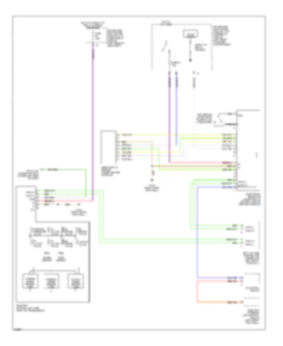
A/T Wiring Diagram, 5 Speed A/T for Mercedes-Benz E500 2005

List of elements for A/T Wiring Diagram, 5 Speed A/T for Mercedes-Benz E500 2005:
- (+)
- (-)
- 1-2/ 4-5 valve
- 2-3 shift valve
- 3-4 shift valve
- Can-c h
- Can-c l
- Circuit 87 relay, chassis
- Data link connector (dlc) (lower left side of dash)
- Di control module
- Diag
- Driver side sam control module with fuse & relay module (left rear of eng compt)
- Driver side sam control module with fuse/relay module (left rear of engine compartment)
- Electric steering lock control module (left front footwell)
- Electronic selector lever module control module (center console)
- Etc control module (right front footwell)
- Fuse 45 7.5a
- Fuse 7.5a
- Gear display sensor (under center console)
- Gnd
- Hot at all times
- Hot with circuit 87 relay chassis energized
- Keyless go start/stop pushbutton (if equipped)
- Left voltage distributor connector (left front door sill)
- Lock up valve
- Modu- lator valve
- Nca
- Rpm sensor
- Shift valve
- Sig
- Solid state
- Start interlock switch
- Temp sensor
- Valve unit (electronic transmission control)
- W15/1 (right front footwell)
A/T Wiring Diagram, 7 Speed A/T for Mercedes-Benz E500 2005
List of elements for A/T Wiring Diagram, 7 Speed A/T for Mercedes-Benz E500 2005:
- B1 brake valve
- B2 brake valve
- B3 brake valve
- Can-c h
- Can-c l
- Circuit 87 relay, chassis
- Data link connector (dlc) (lower left side of dash)
- Di control module
- Diag
- Driver side sam control module with fuse & relay module (left rear of eng compt)
- Driver side sam control module with fuse/relay module (left rear of engine compartment)
- Electric control unit (vgs) (part of transmission)
- Electric steering lock control module (left front footwell)
- Electronic selector lever module control module (center console)
- Fuse 45 7.5a
- Fuse 7.5a
- Gear display sensor (under center console)
- Gnd
- Hot at all times
- Hot with circuit 87 relay chassis energized
- Internal speed sensor (vgs)
- K1 clutch valve
- K2 clutch valve
- K3 clutch valve
- Keyless go start/stop pushbutton (if equipped)
- Left voltage distributor connector (left front door sill)
- Lockup valve
- N.c.
- Nca
- Output speed sensor (vgs)
- Range sensor
- Solid state
- Temp sensor
- Turbine speed sensor (vgs)
- W15/1 (right front footwell)
- Working pressure valve