TRANSMISSION
A/T Wiring Diagram for Mercedes-Benz ML350 Bluetec 4Matic 2014

List of elements for A/T Wiring Diagram for Mercedes-Benz ML350 Bluetec 4Matic 2014:
- (or red)
- (right side of engine compt) (4.6l turbo & 3.5l) w2 w52/11 (3.0l turbo diesel) (right rear of engine compt)
- (under rear of center console) w12
- 3.0l turbo diesel
- 30g
- 4.6l turbo & 3.5l
- Battery compartment prefuse box (under front passenger's seat)
- Can a h
- Can a l
- Can b h
- Can b h ip
- Can b l
- Can c h
- Can c l
- Can e1 h
- Can e1 l
- Clutch control solenoid valve k1
- Clutch control solenoid valve k2
- Clutch control solenoid valve k3
- Computer data lines system
- Direct select lever (if eqipped)
- Electric transmission oil pump
- Electronic ignition switch control unit
- Engine compartment fuse & relay module (right side of engine compt)
- Fully integrated transmission control control unit (in transmission)
- Fuse 15a
- Fuse 5a
- Gear ind
- Hot at all times
- Hot w/ circuit 15 relay energized
- Hot w/ circuit 30g relay energized
- Instrument cluster
- Intelligent servo module (direct select) (left side of transmission housing)
- Internal transmission speed rpm sensor
- Ism
- Lin b12
- Lower control panel control unit
- Mf1
- Mode display
- Multidisk brake control solenoid valve b1
- Multidisk brake control solenoid valve b2
- Multidisk brake control solenoid valve b3
- Multiple fuse 1
- Output shaft rpm sensor
- P not
- Pnk
- Prnd
- Red
- S12
- Sam control unit (right kick panel)
- Selection range sensor
- Steering column module control unit (behind steering wheel)
- Torque converter lockup clutch control solenoid valve
- Transmission
- Transmission mode button
- Transmission oil auxiliary pump control unit (right side of transmission)
- Transmission oil temperature sensor
- Turbine wheel rpm sensor
- W/ eco start/stop function
- W2 (4.6l turbo & 3.5l) (right side of engine compt)
- W52/11 (3.0l turbo diesel) (right rear of engine compt)
- Working pressure control solenoid valve
- X18-c1
- X22/2-c1
- X22/2-c2
- X25/2-c1
- X29/6-c1
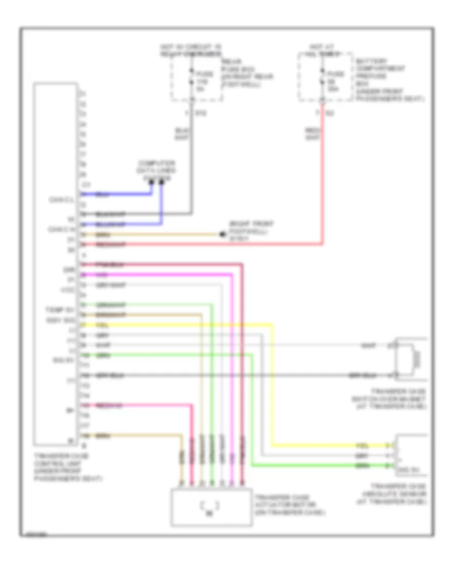
Transfer Case Wiring Diagram for Mercedes-Benz ML350 Bluetec 4Matic 2014
List of elements for Transfer Case Wiring Diagram for Mercedes-Benz ML350 Bluetec 4Matic 2014:
- (+)
- (-)
- (right front footwell) w15/1
- Battery compartment prefuse box (under front passenger's seat)
- Can c h
- Can c l
- Computer data lines system
- Dir
- Fuse 30a
- Fuse 5a
- Hot at all times
- Hot w/ circuit 15 relay energized
- Igsv sig
- Rear fuse box (in right rear footwell)
- S12
- Sig sv
- Temp sv
- Transfer case absolute sensor (at transfer case)
- Transfer case actuator motor (on transfer case)
- Transfer case control unit (under front passenger's seat)
- Transfer case switch over magnet (at transfer case)
- Vcc